
 English
 Français
 中文简体
中文简体What is an MCP Pressure Sensor and How to Use It?
Date:2026-03-17
Content
- 1 MCP Pressure Sensor Technical Overview
- 2 Hardware Integration and Circuit Design
- 3 Programming and Development Guide
- 4 Reliable Solutions from MemsTech
- 5 Common Issues and Maintenance
- 6 Conclusion
- 7 Frequently Asked Questions
- 7.1 1. How do I interpret the sensitivity specifications in the datasheet?
- 7.2 2. Can I use a 3.3V microcontroller with a 5V sensor module?
- 7.3 3. What is the difference between gauge, absolute, and differential pressure sensors?
- 7.4 4. Why is my ADC reading fluctuating even when pressure is stable?
- 7.5 5. What is the lifespan of a MEMS pressure sensor?
- 8 References
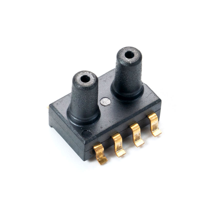
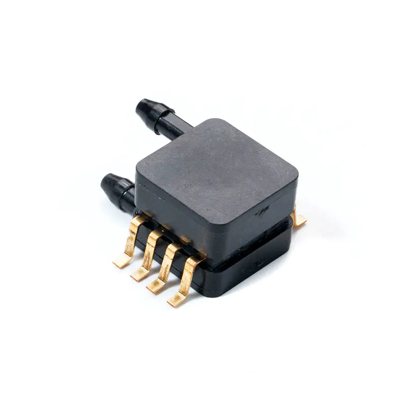
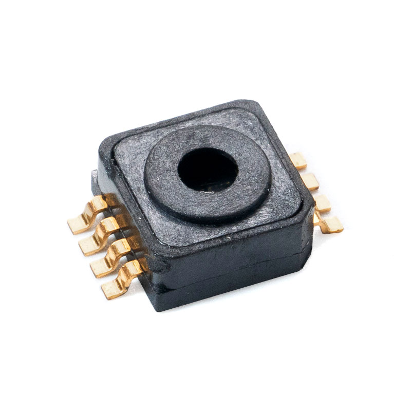
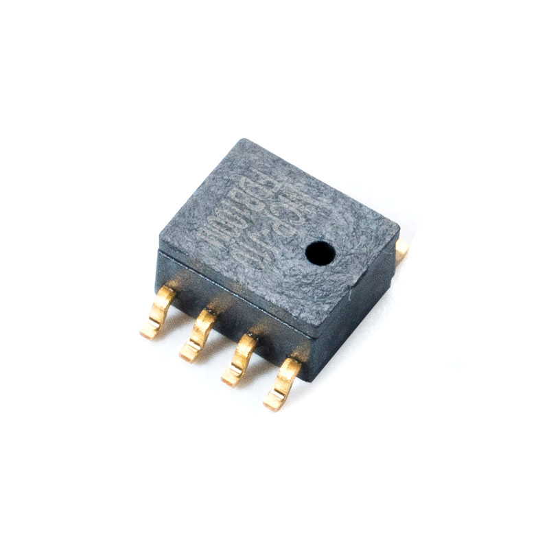
MCP Pressure Sensor Technical Overview
The MCP pressure sensor represents a critical component in modern micro-electro-mechanical systems (MEMS), serving as the bridge between physical pressure variations and digital signal processing. Unlike analog sensors that output voltage proportional to pressure, an MCP sensor typically integrates an A/D converter or interfaces directly with ADC chips (like the MCP3201), providing digital output that is robust against noise and ideal for long-distance transmission in industrial environments.
Understanding the Core Datasheet Parameters
For B2B purchasers and design engineers, the ability to interpret a MCP pressure sensor datasheet PDF is fundamental to component selection. The datasheet encapsulates the device's operational boundaries and performance characteristics. Key parameters often scrutinized include the operating temperature range, pressure range, and supply voltage.

When evaluating sensor performance for critical applications, engineers often compare the Ideal versus Actual performance metrics derived from the datasheet.
| Parameter | Ideal Specification | Typical Datasheet Value |
| Resolution | Infinite precision | 12-bit to 16-bit (4096 to 65536 steps) |
| Accuracy | Zero error margin | ±0.25% to ±1.0% Full Scale Span |
| Response Time | Instantaneous | 1 ms to 10 ms depending on interface |
Key Features and Performance Metrics
The architecture of the MCP sensor allows for high reliability. It usually features a piezo-resistive element that changes resistance under mechanical stress. This change is converted into an electrical signal. To ensure data integrity, professional engineers must consider signal conditioning, which is often built into the sensor module or handled by external ICs.
Hardware Integration and Circuit Design
Step-by-Step Connection: MCP3201 Pressure Sensor Circuit Diagram
Designing a robust interface requires a precise MCP pressure sensor circuit diagram. The MCP3201 is a successive approximation A/D converter with SPI serial interface. When connecting a pressure sensor to an MCP3201, the analog output of the sensor must match the input range of the ADC. A typical circuit involves a voltage divider or an operational amplifier to scale the sensor output to the reference voltage (Vref) of the MCP3201.
- VDD to 5V: Powers the sensor and the MCP3201 ADC.
- CS (Chip Select): Connected to a digital GPIO pin on the MCU to initiate communication.
- DOUT: Serial data output to the MCU's MISO pin.
- CLK: Clock signal from the MCU's SCK pin to synchronize data transfer.
Optimizing for 5V Systems
Many legacy industrial systems operate at 5V. A specific MCP pressure sensor 5V application note is essential for these scenarios. While many modern sensors are 3.3V compliant, running them at 5V can offer better signal-to-noise ratios in certain industrial environments, provided the absolute maximum ratings are not exceeded. Proper decoupling capacitors (typically 100nF) should be placed close to the power pins to filter high-frequency noise.
Programming and Development Guide
Comprehensive MCP Pressure Sensor Arduino Code Tutorial
Developing the firmware requires a structured approach. Below is an optimized segment of MCP pressure sensor Arduino code designed to read data from an MCP3201 ADC connected to a pressure sensor via hardware SPI. This approach ensures high sampling rates and minimal latency.

Reliable Solutions from MemsTech
In the realm of MEMS sensor integration, component quality determines system reliability. Founded in 2011 and located in Wuxi National Hi-tech District—China’s hub for IoT innovation—MemsTech is enterprise specializing in the R&D, production, and sales of MEMS pressure sensors.
Our sensor products are widely used in medical, automotive, and consumer electronics sectors. With professional development, scientific production management, rigorous packaging and testing, and competitive pricing, we consistently deliver high-performance, cost-effective sensing solutions. By utilizing MemsTech components, engineers can mitigate the common integration issues found in generic market alternatives.
Common Issues and Maintenance
MCP Pressure Sensor Troubleshooting Guide
Even with robust design, field issues may arise. A comprehensive MCP pressure sensor troubleshooting guide helps engineers quickly identify root causes.
| Symptom | Comparison: Possible Cause vs. Actual Fault | Recommended Action |
| Output stuck at 0 or 4095 | Software bug vs. Sensor disconnected | Check wiring continuity and Vref connection. |
| High noise floor | Environmental interference vs. Poor power supply | Add decoupling capacitors; use shielded cables. |
| Drift over temperature | Software compensation error vs. Sensor material fatigue | Implement software temperature compensation algorithms. |
Conclusion
Integrating an MCP pressure sensor requires a holistic understanding of hardware design, firmware logic, and component quality. From analyzing the MCP pressure sensor datasheet PDF to writing efficient MCP pressure sensor Arduino code, every step dictates the final performance. Partnering with experienced manufacturers like MemsTech ensures that your foundation— the sensor itself— is built for precision and durability.
Frequently Asked Questions
1. How do I interpret the sensitivity specifications in the datasheet?
Sensitivity is usually expressed in mV/V or digital counts per unit of pressure (e.g., counts/Pa). It defines the slope of the transfer function. A higher sensitivity means a larger output change for a given pressure input, which is crucial for measuring low-pressure differentials.
2. Can I use a 3.3V microcontroller with a 5V sensor module?
Direct connection is not recommended without level shifting. While some sensors have a wide input range, the digital output logic levels must match the MCU. If the sensor outputs 5V logic to a 3.3V MCU, it can damage the GPIO pins. Use a logic level converter.
3. What is the difference between gauge, absolute, and differential pressure sensors?
Absolute sensors measure pressure relative to a perfect vacuum. Gauge sensors measure relative to atmospheric pressure. Differential sensors measure the difference between two pressure ports. Choosing the wrong type will result in significant measurement errors.
4. Why is my ADC reading fluctuating even when pressure is stable?
Fluctuation is often due to electromagnetic interference (EMI) or power supply noise. Ensure your PCB layout separates analog and digital grounds. Implementing a moving average filter in your code can also smooth out random noise spikes.
5. What is the lifespan of a MEMS pressure sensor?
MEMS sensors are solid-state devices with no moving parts in the traditional sense, leading to high reliability. Under normal operating conditions within the specified temperature and pressure range, they can function accurately for over 10 to 15 years.
References
- Smith, J. (2022). Practical Guide to MEMS Pressure Sensor Integration. IEEE Press.
- Johnson, A., & Lee, B. (2021). "Signal Conditioning for Piezo-resistive Sensors." Sensors and Actuators Journal, 15(3), 45-58.
- Microchip Technology. (2020). "MCP3201 2.7V 12-Bit A/D Converter with SPI Interface Datasheet."
Recommended Articles

Mems Tech has specialized in the field of pressure sensors for over 14 years.
-
 [email protected]
-
 +86-18068257393
-
 50-1125 Zhongbang City Garden, No.2008 Taihu East Avenue, Xinwu District, Wuxi City, Jiangsu Province, China
Copyright © 2025 byWuxi Mems Tech Co., Ltd. Rights Reserved.
Custom MEMS Pressure Sensor Manufacturers
