
 English
 Français
 中文简体
中文简体MEMS Pressure Sensors: A Comprehensive Guide to Technology, Applications, and Selection
Date:2025-11-12
Content
- 1 Introduction to MEMS Pressure Sensors
- 2 1.1 What are MEMS Pressure Sensors?
- 3 1.2 Historical Development of MEMS Pressure Sensors
- 4 Technology and Working Principles
- 5 2.1 Underlying Physics
- 6 2.2 Fabrication Process
- 7 2.3 Types of MEMS Pressure Sensors
- 8 Key Performance Parameters
- 9 3.1 Sensitivity and Accuracy
- 10 3.2 Pressure Range and Overpressure
- 11 3.3 Temperature Effects
- 12 3.4 Long-term Stability and Reliability
- 13 Applications of MEMS Pressure Sensors
- 14 4.1 Automotive Industry
- 15 4.2 Medical Devices
- 16 4.3 Industrial Automation
- 17 4.4 Consumer Electronics
- 18 Selecting the Right MEMS Pressure Sensor
- 19 5.1 Application Requirements
- 20 5.2 Sensor Specifications
- 21 5.3 Packaging and Mounting
- 22 5.4 Cost Considerations
- 23 Latest Innovations and Future Trends
- 24 6.1 Advanced Materials and Fabrication Techniques
- 25 6.2 Integration with IoT and Wireless Technology
- 26 6.3 Miniaturization and Low Power Consumption
- 27 Top MEMS Pressure Sensor Products
- 28 Conclusion
- 29 8.1 Summary of Key Points
- 30 8.2 Future Outlook
Introduction to MEMS Pressure Sensors
1.1 What are MEMS Pressure Sensors?
Definition and Basic Principles
MEMS Pressure Sensors are micro-fabricated devices designed to measure the pressure of a fluid (liquid or gas). MEMS stands for Micro-Electro-Mechanical Systems, referring to the technology of miniaturized devices built using micro-fabrication techniques, similar to those used in integrated circuit (IC) manufacturing.
The basic principle involves a diaphragm (a thin, micro-machined membrane, often made of silicon) that deflects when subjected to a pressure difference. This deflection is then converted into an electrical signal using various sensing principles, most commonly:
- Piezoresistive: Changes in the electrical resistance of diffused or implanted strain gauges on the diaphragm.
- Capacitive: Changes in the capacitance between the deflected diaphragm and a fixed reference electrode.
Advantages over Traditional Pressure Sensors
MEMS pressure sensors offer significant advantages compared to traditional, bulkier pressure sensors (e.g., those using foil strain gauges or macro-scale diaphragms):
- Miniaturization and Size: They are incredibly small, often less than a millimeter in size, allowing for integration into compact devices and tight spaces.
- Mass Production and Low Cost: Fabricated using semiconductor batch processing techniques (photolithography, etching, etc.), which enables high-volume, low-cost manufacturing.
- High Sensitivity and Accuracy: The small, highly controlled structures allow for excellent resolution and precise measurements.
- Low Power Consumption: Their small size and reduced mass typically lead to lower power requirements, ideal for battery-powered and portable devices.
- High Integration Potential: Can be easily integrated with on-chip circuitry (ASICs) for signal conditioning, temperature compensation, and digital output, creating a complete System-in-Package (SiP).
1.2 Historical Development of MEMS Pressure Sensors
Key Milestones and Innovations
The history of MEMS pressure sensors is closely linked to the development of semiconductor manufacturing and micromachining techniques.
| Time Period | Key Milestones and Innovations | Description |
| 1954 | Discovery of Piezoresistive Effect in Silicon | C.S. Smith's discovery that the electrical resistance of silicon and germanium changes significantly under mechanical stress (Piezoresistive Effect) became the foundation for the first generation of silicon-based pressure sensors. |
| 1960s | First Silicon Pressure Sensor | Early silicon pressure sensors were demonstrated, leveraging the discovered piezoresistive effect. These were bulky, primarily using bulk micromachining. |
| 1980s | Commercialization and Micromachining | The emergence of early forms of surface micromachining and the first commercial, high-volume silicon pressure sensors (e.g., disposable blood pressure transducers for medical use, and manifold absolute pressure (MAP) sensors for engine control). The term MEMS (Micro-Electro-Mechanical Systems) was also formally introduced during this decade. |
| 1990s | Mass Production and Integration | Advances in fabrication, such as Deep Reactive Ion Etching (DRIE) (e.g., the Bosch process, patented in 1994), allowed for the creation of high-aspect-ratio, complex 3D structures. This led to the mass production of low-cost, robust sensors for automotive (like those in airbag systems and early engine management) and consumer electronics. |
| 2000s-Present | Miniaturization and Consumer Boom | Focus shifted to highly miniaturized sensors (e.g., barometric sensors) with integrated ASICs for signal processing and temperature compensation, enabling their widespread adoption in smartphones, wearables, and the Internet of Things (IoT). Capacitive and resonant sensing gained prominence alongside piezoresistive technology for better stability and lower power. |
Impact on Various Industries
The shift from traditional, large-scale sensors to tiny, mass-producible MEMS pressure sensors has had a transformative impact across multiple sectors:
- Automotive: MEMS sensors were critical in the development of modern electronic engine control (Engine Control Units, ECU) and safety systems. They enabled the mandatory adoption of Tire Pressure Monitoring Systems (TPMS) due to their low cost and small size, significantly enhancing vehicle safety and fuel efficiency.
- Medical: The miniaturization allowed for the creation of disposable blood pressure sensors for invasive monitoring (catheters), drastically improving sanitation and reducing cross-contamination in hospitals. They are also essential in portable ventilators, infusion pumps, and continuous health monitoring devices.
- Consumer Electronics: MEMS barometric pressure sensors made features like indoor navigation (determining floor level in buildings) and accurate altitude measurement in drones and fitness trackers possible. This has been a major driver in the growth of the mobile and wearable device markets.
- Industrial/IoT: The low power consumption and small form factor are key enablers for the Industrial Internet of Things (IIoT), allowing for the deployment of wireless pressure sensor nodes in factory automation, process control, and environmental monitoring systems. This drives efficiency and predictive maintenance.
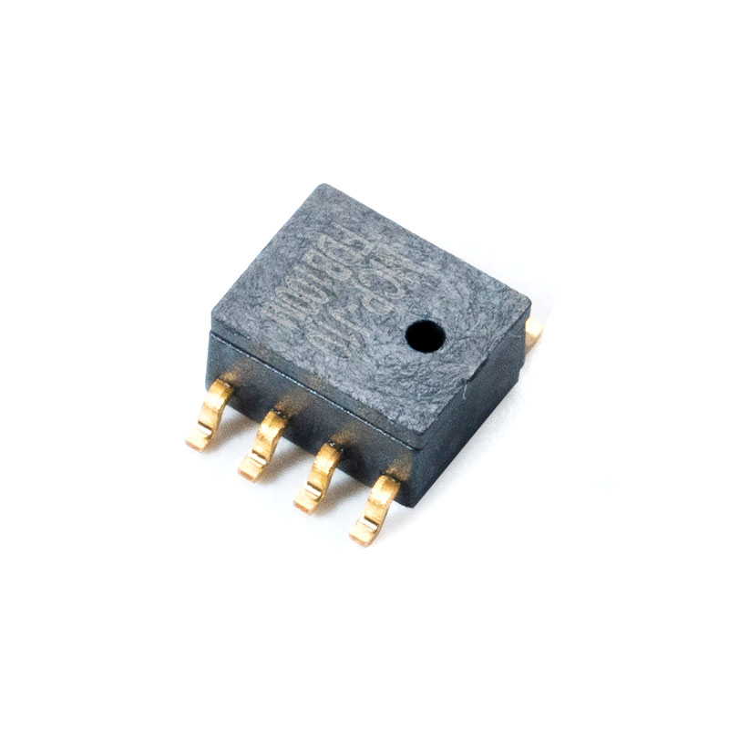
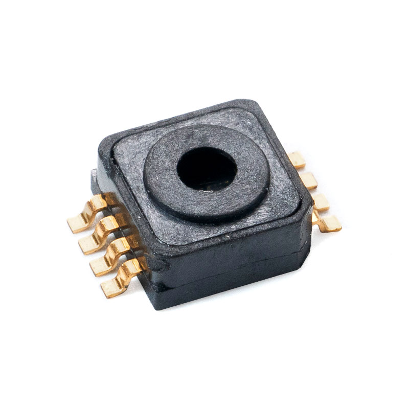
MCP-J10, J11, J12 Absolute pressure sensor
Technology and Working Principles
2.1 Underlying Physics
MEMS pressure sensors convert the mechanical deflection of a diaphragm into a measurable electrical signal using different physical principles.
Piezoresistive Effect
- Principle: The piezoresistive effect states that the electrical resistivity of a semiconductor material (like silicon) changes when mechanical stress () is applied.
- Mechanism: In a piezoresistive sensor, resistors (often made of doped silicon or polycrystalline silicon) are diffused or implanted onto the surface of the silicon diaphragm. When pressure causes the diaphragm to deflect, these resistors are strained (), leading to a change in their resistance ().
- Output: Typically, four resistors are arranged in a Wheatstone bridge configuration to maximize sensitivity and provide temperature compensation, yielding a voltage output proportional to the applied pressure.
Capacitive Sensing
- Principle: Capacitive sensors measure pressure based on the change in electrical capacitance ().
- Mechanism: The sensor consists of two parallel electrodes: the pressure-sensing diaphragm and a fixed back electrode. When pressure is applied, the diaphragm deflects, changing the distance () between the two electrodes. Since capacitance is inversely proportional to the distance (), the applied pressure is measured by the change in .
- Advantages: Generally offers higher stability, lower power consumption, and lower temperature sensitivity compared to piezoresistive types, but requires more complex readout circuitry.
Resonant Sensing
- Principle: Resonant sensors measure pressure based on the change in the natural resonant frequency () of a micro-mechanical structure (e.g., a beam or diaphragm).
- Mechanism: A micro-mechanical resonator is driven to oscillate. When pressure is applied, the stress/strain in the structure changes, which in turn alters its stiffness and mass distribution. This shift in mechanical properties causes a change in the resonant frequency, .
- Advantages: Extremely high resolution and long-term stability, as frequency is an inherently digital and robust measurement parameter.
2.2 Fabrication Process
MEMS pressure sensors are manufactured using highly specialized micromachining techniques adapted from the semiconductor industry.
Micromachining Techniques (Bulk vs. Surface)
- Bulk Micromachining:
- Process: Involves selectively etching the bulk of the silicon wafer to create 3D structures like the pressure-sensing diaphragm and reference chamber.
- Methods: Uses anisotropic wet etchants (like or ) or dry etching techniques like Deep Reactive Ion Etching (DRIE).
- Result: Diaphragm thickness is often determined by the depth etched into the substrate.
- Surface Micromachining:
- Process: Involves depositing and patterning thin films (polysilicon, silicon nitride, etc.) on the surface of the wafer to create mechanical structures. A sacrificial layer is deposited and then selectively removed (etched) to free the mechanical structure (e.g., the movable plate in a capacitive sensor).
- Result: Structures are typically thinner, smaller, and fabricated with greater integration density, often used for accelerometers but also for some capacitive pressure sensors.
Materials Used (Silicon, Silicon-on-Insulator)
- Silicon (): The primary material. It possesses excellent mechanical properties (high strength, low mechanical hysteresis, similar to steel), is a good semiconductor (allowing for piezoresistive doping), and its fabrication processes are highly mature and cost-effective.
- Silicon-on-Insulator (): A composite wafer structure consisting of a thin layer of silicon (device layer) on top of an insulating layer (Buried Oxide, ) on a bulk silicon substrate.
- Advantage: Offers superior performance for harsh environments (high temperature, radiation) and enables precise control over the diaphragm thickness and electrical isolation, which is crucial for high-performance sensors.
2.3 Types of MEMS Pressure Sensors
Pressure sensors are classified based on the type of pressure they measure relative to a reference point.
- Absolute Pressure Sensors:
- Reference: Measure pressure relative to a perfect vacuum (0 absolute) sealed inside the sensor's reference cavity.
- Use Case: Altitude measurement, barometric pressure in weather stations and phones.
- Gauge Pressure Sensors:
- Reference: Measure pressure relative to the ambient atmospheric pressure outside the sensor.
- Use Case: Tire pressure, hydraulic systems, industrial tank levels. (At standard atmospheric pressure, the output is zero.)
- Differential Pressure Sensors:
- Reference: Measure the difference in pressure between two distinct ports or points.
- Use Case: Measuring flow rate (by measuring pressure drop across a restriction), HVAC filter monitoring.
- Sealed Pressure Sensors:
- Reference: A subset of Gauge sensors where the reference cavity is sealed at a specific pressure (usually standard atmospheric pressure at sea level), making them insensitive to variations in local atmospheric pressure.
- Use Case: Where the output needs to be a constant reference pressure regardless of weather or altitude changes.
Key Performance Parameters
3.1 Sensitivity and Accuracy
Defining Sensitivity and its Importance
- Sensitivity is the measure of the sensor's output signal change () per unit change in pressure (). It is typically expressed in units like mV/V/psi (millivolts per volt excitation per pound-force per square inch) or mV/Pa.
- Formula:
- Importance: Higher sensitivity means a larger electrical signal for a given pressure change, making the signal easier to measure, condition, and resolve, especially for low-pressure applications.
Factors Affecting Accuracy
Accuracy defines how closely the sensor's measured output matches the true value of the pressure. It is often a composite of several error sources:
- Non-linearity (NL): The deviation of the actual output curve from an ideal straight-line response.
- Hysteresis: The difference in output when the same pressure point is approached by increasing pressure versus decreasing pressure.
- Offset/Zero-Point Error: The output signal when zero pressure is applied.
- Temperature Effects: Changes in output due to variations in ambient temperature (addressed in 3.3).
Calibration Techniques
To ensure high accuracy, sensors undergo calibration:
- Trimming: Adjusting on-chip resistors (for piezoresistive) or implementing digital look-up tables (for smart sensors) to minimize initial offset and sensitivity variations.
- Temperature Compensation: Measuring the sensor's response across a temperature range and applying a correction algorithm (often digitally in the integrated ASIC) to correct for temperature-induced errors.
3.2 Pressure Range and Overpressure
Selecting Appropriate Pressure Range
- The Pressure Range is the specified band of pressure (e.g., $0$ to $100 psi) over which the sensor is designed to operate and meet its performance specifications.
- Selection: The ideal sensor range should match the maximum expected operating pressure of the application, plus a safety margin, to ensure the highest resolution and best accuracy (as accuracy is often specified as a percentage of the Full Scale Output, FSO).
Understanding Overpressure Limits
- Maximum Operating Pressure: The highest pressure the sensor can be continuously subjected to without causing a permanent shift in performance specifications.
- Overpressure Limit (or Burst Pressure): The maximum pressure the sensor can withstand without physical damage or catastrophic failure (e.g., rupture of the diaphragm).
- Selecting a sensor with a high overpressure rating is crucial for applications where pressure spikes or sudden surges are common, to prevent system failure.
3.3 Temperature Effects
Temperature Sensitivity and Compensation
- Temperature Sensitivity: All silicon-based MEMS sensors are inherently sensitive to temperature variations. This causes two main effects:
- Temperature Coefficient of Offset (TCO): The zero-pressure output changes with temperature.
- Temperature Coefficient of Span (TCS): The sensitivity of the sensor changes with temperature.
- Compensation: Modern smart MEMS sensors employ integrated ASICs (Application-Specific Integrated Circuits) to measure the chip temperature and digitally apply correction algorithms (compensation) to the raw pressure data, largely eliminating these errors across the operating temperature range.
Operating Temperature Range
- This is the range of ambient temperatures (e.g., to ) within which the sensor is guaranteed to meet all its published performance specifications, including compensated accuracy.
3.4 Long-term Stability and Reliability
Drift and Hysteresis Considerations
- Drift (Zero-point Drift): The change in the sensor's zero-pressure output over a long period of time (e.g., months or years), even when stored under constant conditions. This affects the long-term accuracy and may necessitate recalibration.
- Hysteresis (Pressure Hysteresis): The output difference at a specific pressure point when reaching it via increasing pressure versus decreasing pressure. High hysteresis indicates poor elastic behavior of the diaphragm material or package stress.
Factors Influencing Long-term Reliability
- Packaging Stress: Mechanical stress induced by the sensor packaging material (e.g., epoxy, plastic) or the mounting process can change over time due to thermal cycling or moisture, leading to drift.
- Media Compatibility: The sensor material must be compatible with the fluid it is measuring (the "media"). Exposure to corrosive or moisture-laden media without adequate protection (e.g., a gel coating or metallic barrier) will rapidly degrade the sensor's performance.
- Material Fatigue: Repeated stress cycles from pressure changes can lead to material fatigue, eventually affecting the sensor's mechanical properties and stability.
Applications of MEMS Pressure Sensors
4.1 Automotive Industry
MEMS pressure sensors are critical components in modern vehicles, supporting both performance and safety systems.
- Tire Pressure Monitoring Systems (TPMS): Pressure sensors embedded within each tire's valve stem wirelessly monitor tire pressure. This is essential for safety (preventing blowouts) and efficiency (optimizing fuel economy).
- Manifold Absolute Pressure (MAP) Sensors: These measure the absolute pressure in the engine's intake manifold. The data is sent to the Engine Control Unit (ECU) to calculate the density of the air entering the engine, allowing for the precise metering of fuel injection and ignition timing.
- Brake Pressure Monitoring: Used in hydraulic braking systems, especially those with Electronic Stability Control (ESC) and Anti-lock Braking Systems (ABS), to accurately monitor and control the hydraulic pressure applied to the brake lines.
- Exhaust Gas Recirculation (EGR) and Particulate Filters (DPF/GPF): Differential pressure sensors measure pressure drops across filters and valves to monitor emissions control systems, ensuring compliance with environmental regulations.
4.2 Medical Devices
Miniaturization and reliability are paramount in medical applications, where MEMS sensors contribute to patient safety and diagnosis.
- Blood Pressure Monitoring:
- Invasive: Catheter-tip sensors (often piezoresistive) are used in intensive care or surgery to measure blood pressure directly within arteries, providing highly accurate, real-time data.
- Non-Invasive: Essential components in standard electronic blood pressure cuffs and continuous wearable monitoring devices.
- Infusion Pumps: Pressure sensors monitor the fluid line pressure to ensure accurate drug delivery, detect potential blockages, or confirm the line is open.
- Respiratory Devices (e.g., Ventilators, CPAP machines): Highly sensitive differential pressure sensors are used to measure airflow, control the pressure and volume of air delivered to the patient's lungs, and monitor inhalation/exhalation cycles.
4.3 Industrial Automation
In industrial settings, MEMS sensors replace traditional, larger sensors to improve precision, reduce maintenance costs, and enable remote monitoring.
- Process Control: Used in pipelines, reactors, and storage tanks to maintain constant pressure levels, which is crucial for chemical, oil and gas, and pharmaceutical manufacturing processes.
- Pressure Transmitters: MEMS sensing elements are integrated into rugged transmitters that provide standardized digital or analog output signals for remote monitoring and integration into Distributed Control Systems (DCS).
- HVAC Systems (Heating, Ventilation, and Air Conditioning): Differential pressure sensors monitor pressure drops across air filters to determine when they need replacement (improving energy efficiency) and measure air flow velocity for precise climate control.
4.4 Consumer Electronics
MEMS sensors enable many of the smart features users rely on in portable devices.
- Barometric Pressure Sensors in Smartphones: Measure atmospheric pressure to provide:
- Altitude Tracking: For fitness and outdoor apps.
- Indoor Navigation (Z-Axis): Allows maps to determine the user's floor level in a multi-story building.
- Weather Forecasting: Used to predict localized weather changes.
- Wearable Devices: Used in smartwatches and fitness trackers for highly accurate altitude gain tracking during activities like hiking or climbing stairs.
- Drones: Barometric sensors provide highly accurate altitude hold functionality, which is critical for stable flight and navigation.
Selecting the Right MEMS Pressure Sensor
5.1 Application Requirements
The first step is a thorough definition of the operational environment and measurement needs.
Identifying Specific Needs
- Pressure Type: Determine the required measurement type: Absolute (relative to vacuum), Gauge (relative to ambient air), or Differential (difference between two points).
- Pressure Range: Define the Minimum and Maximum expected operating pressures. The sensor's full-scale range should comfortably bracket these values, including potential transient spikes (→ see Overpressure).
- Accuracy and Resolution: Specify the required accuracy (e.g., ) and the smallest pressure change that must be reliably detected (resolution). Higher accuracy often means higher cost and larger package size.
- Media Compatibility: Identify the substance (gas, liquid, or corrosive chemical) whose pressure is being measured. The sensor's wetted materials must be chemically compatible with the media to prevent corrosion and failure.
Environmental Conditions
- Operating Temperature Range: The sensor must perform reliably across the expected ambient and media temperature extremes. This is crucial for selecting a sensor with proper temperature compensation.
- Humidity and Contaminants: Determine if the sensor is exposed to moisture, dust, or other contaminants. This dictates the required Ingress Protection (IP) rating and whether a protected/sealed package is necessary.
5.2 Sensor Specifications
Once application needs are known, the manufacturer's data sheet must be scrutinized.
Evaluating Key Parameters
- Sensitivity and Linearity: Ensure the sensitivity is sufficient for the required resolution. Check the linearity to guarantee accurate measurements across the entire pressure range.
- Total Error Band (TEB): This is the single most important parameter, as it defines the worst-case accuracy over the entire compensated temperature range and includes linearity, hysteresis, and thermal errors. It gives a realistic performance picture.
- Proof Pressure/Burst Pressure: Verify that the sensor's overpressure limit is safely above the maximum expected pressure, including any potential hydraulic shock or pressure spikes.
Power Consumption Considerations
- For battery-powered, portable, or IoT devices, low power consumption ( level) is essential. Capacitive sensors or smart sensors with advanced power-down modes are often preferred over continuous-power piezoresistive types.
- The choice between analog and digital output (e.g., , ) also influences power consumption and ease of system integration.
5.3 Packaging and Mounting
The sensor's package is critical for protecting the MEMS die and interfacing with the application.
Available Packaging Options
- Surface Mount Devices (SMD/LGA/QFN): Small, low-cost packages for direct soldering onto a PCB, common in consumer and medical devices (e.g., barometric sensors).
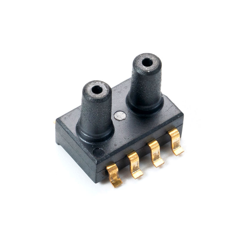
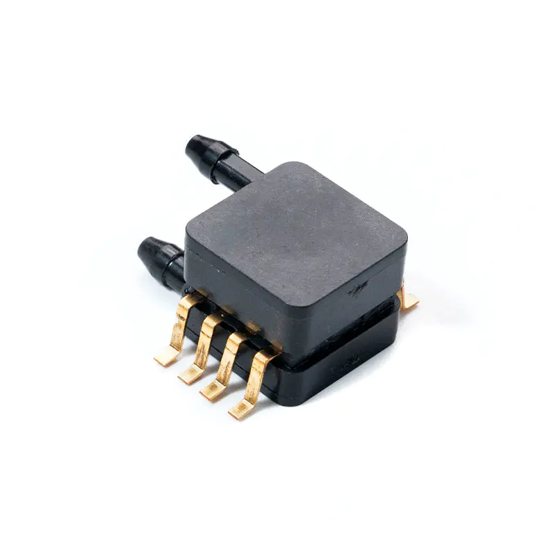
- Ported/Barbed Packages: Plastic or ceramic packages with pressure ports (barbs or threads) for connecting tubing, common in low-pressure and flow applications.
- Module/Transmitter Housing: Robust, often metallic, housings with threaded ports and connectors for harsh industrial environments, often containing media isolation (e.g., oil-filled cavity).
Mounting Considerations for Optimal Performance
- Minimizing Mechanical Stress: The sensor package is sensitive to external stress. When mounting on a PCB (especially with screws), ensure that excessive torque or uneven stress is avoided, as this can cause a shift in the zero-point (offset).
- Venting: Gauge pressure sensors require a vent hole to ambient air. This vent must be protected from liquid and contaminants, often requiring a specialized package design or protective membrane (e.g., a gel coating).
- Thermal Management: Place the sensor away from heat sources (CPUs, power components) to minimize temperature gradients that could exceed the compensated temperature range.
5.4 Cost Considerations
Cost is always a factor, but the lowest unit price is rarely the best long-term solution.
Balancing Performance and Cost
- Higher accuracy, wider temperature compensation, and media isolation all add to the unit cost. Avoid over-specifying; only select the performance level that the application truly requires.
- Uncompensated vs. Compensated: A raw, uncompensated sensor die is cheaper but requires the user to develop and implement complex, costly calibration and temperature compensation algorithms in their own system, increasing development time. A factory-calibrated, compensated sensor (smart sensor) has a higher unit cost but significantly lowers system-level integration cost.
Long-term Cost of Ownership
- Consider the total cost, including calibration time, potential warranty claims due to drift or failure in harsh environments, and the cost of replacing or recalibrating failed units. A more robust, higher-priced sensor that offers better long-term stability and reliability often yields a lower total cost of ownership.
Latest Innovations and Future Trends
6.1 Advanced Materials and Fabrication Techniques
Innovations are focused on improving sensor resilience, stability, and sensitivity.
Use of New Materials (e.g., Silicon Carbide (), Graphene, )
- Silicon Carbide (): Being explored for harsh environment applications (e.g., down-hole drilling, gas turbines, engine compartments) due to its ability to operate reliably at extremely high temperatures (exceeding ) where conventional silicon sensors would fail.
- Silicon-on-Insulator (): Increasingly adopted for high-performance and automotive safety-critical applications (e.g., ADAS, brake-line monitoring) as it offers better electrical isolation and thermal stability over a wide temperature range (up to ).
- Graphene: Research is underway to leverage the superior mechanical strength and electronic properties of graphene to create highly sensitive, ultra-low-power sensors that are exceptionally thin.
Advanced Micromachining Processes
- Through-Silicon Via (): Enables 3D stacking of the MEMS die and the ASIC, significantly reducing the package footprint (Z-height) and boosting Electromagnetic Interference (EMI) immunity.
- Beam-Membrane-Island Design: A new diaphragm structure for minute differential pressure sensors (Z-height), offering extremely high sensitivity for medical ventilators and industrial flow meters.
6.2 Integration with IoT and Wireless Technology
The convergence of MEMS sensors with connectivity is the primary driver for industrial and consumer growth.
- Wireless Pressure Sensors (LoRaWAN, ): MEMS pressure sensors are integrated with wireless communication modules (like for long range/low power or for cellular connectivity) to form standalone wireless pressure transmitters.
- Remote Monitoring Applications: These wireless nodes eliminate costly cabling, enabling the rapid deployment of dense sensor networks in industrial settings (IIoT) for predictive maintenance (monitoring subtle pressure drifts to predict equipment failure) and remote process control.
- Edge AI and Sensor Fusion: Modern "smart" sensors are incorporating machine learning (ML) cores or integrated ASICs that can process and analyze data (e.g., temperature compensation, filtering, self-diagnostics) directly on the chip (at the "edge"). This reduces data transmission, lowers power consumption, and enables faster, localized decision-making.
6.3 Miniaturization and Low Power Consumption
Miniaturization remains a core competitive factor, especially for consumer and medical markets.
- Trends in Sensor Miniaturization: Continued reduction in die size and package size (down to in some cases) facilitates integration into smaller wearables, hearables, and implantable medical devices.
- Ultra-Low Power Designs: Shift toward capacitive and resonant sensing technologies, which generally consume less power than piezoresistive types. Modern designs are achieving standby currents in the sub- range, critical for extending battery life in IoT end nodes.
- "Pressure + X" Integration: Integration of the pressure sensor with other functionalities (e.g., temperature, humidity, gas sensing) in a single System-in-Package (SiP) to save space and simplify design.
Top MEMS Pressure Sensor Products
| Sensor/Series | Manufacturer | Primary Application | Key Technology/Feature |
| Bosch BMP388 | Bosch Sensortec | Consumer, Drone, Wearable | High-accuracy barometric pressure/altitude measurement ( relative accuracy); very small, low-power. |
| Infineon DPS310 | Infineon Technologies | Consumer, , Navigation | Capacitive sensing for high stability and low noise; excellent temperature stability, designed for mobile and weather applications. |
| STMicroelectronics LPS22HB | STMicroelectronics | Consumer, Industrial, Wearable | Ultra-compact, low-power absolute pressure sensor with digital output ((/)); often used for water-resistant mobile devices. |
| TE Connectivity MS5837 | TE Connectivity | Altimeter, Dive Computers, High-Resolution | Digital Altimeter/Depth sensor; gel-filled, water-resistant design optimized for harsh media and underwater applications. |
| Amphenol NovaSensor NPA-100B | Amphenol Advanced Sensors | Medical, Industrial, Low-Pressure OEM | High-reliability, piezoresistive-based, small form factor, often used in medical devices like CPAP and flowmeters. |
| Murata SCC1300 series | Murata Manufacturing Co. | Automotive (, ), Industrial | High-performance, MEMS technology with rating, known for superior stability in safety-critical applications. |
| Honeywell ABPM series | Honeywell | Industrial, Medical, Absolute/Barometric | Highly accurate, stable digital barometric/absolute sensors; known for high total error band (TEB) performance. |
| First Sensor HCE series | TE Connectivity (acquired First Sensor) | Medical (CPAP), Low-Differential Pressure | Piezoresistive sensing, often used for highly sensitive low-pressure and flow measurements in medical and HVAC. |
| All Sensors DLHR series | All Sensors | Ultra-Low Pressure, Medical | High-resolution low-pressure sensors with Technology for superior performance in low-pressure and medical markets. |
| Merit Sensor Systems BP series | Merit Sensor Systems | Harsh Media, High Pressure | Media-isolated pressure sensor die for high-volume automotive and industrial applications requiring harsh media compatibility. |
Conclusion
8.1 Summary of Key Points
- Technology: MEMS pressure sensors miniature, batch-fabricated devices, primarily using the piezoresistive or capacitive effect to measure pressure via diaphragm deflection.
- Advantages: They offer superior miniaturization, low cost (due to batch processing), low power consumption, and high integration potential compared to traditional sensors.
- Key Metrics: Selection is governed by parameters like Total Error Band (TEB), Overpressure Limit, and media compatibility, ensuring reliable performance across the required pressure and temperature range.
- Applications: They are foundational to modern technology, enabling critical functions in Automotive (TPMS, MAP), Medical (blood pressure, ventilators), Industrial (process control, HVAC), and Consumer Electronics (altitude in smartphones, drones).
8.2 Future Outlook
The future of MEMS pressure sensing is defined by advanced integration, connectivity, and resilience:
- Smart Sensing: The trend toward integrating AI/ML at the edge will continue, allowing sensors to provide actionable insights rather than just raw data, driving further growth in IIoT.
- Harsh Environments: The adoption of advanced materials like SiC and SOI will extend sensor use into more extreme temperature and pressure environments, particularly in electric vehicles (EV) thermal management and high-pressure industrial processes.
- Ubiquity and Cost Reduction: Continued refinement of fabrication techniques (TSV, advanced micromachining) will lead to ever-smaller, more cost-effective devices, accelerating their penetration into new markets like smart farming, energy harvesting, and micro-robotics.
Recommended Articles

Mems Tech has specialized in the field of pressure sensors for over 14 years.
-
 [email protected]
-
 +86-18068257393
-
 50-1125 Zhongbang City Garden, No.2008 Taihu East Avenue, Xinwu District, Wuxi City, Jiangsu Province, China
Copyright © 2025 byWuxi Mems Tech Co., Ltd. Rights Reserved.
Custom MEMS Pressure Sensor Manufacturers
