
 English
 Français
 中文简体
中文简体What Is a Medium Pressure Sensor?
Date:2026-03-24
Content
- 1 1. How Does a Medium Pressure Sensor Work?
- 2 2. Medium Pressure Sensor vs High Pressure Sensor
- 3 3. Key Applications by Industry
- 4 4. How to Select the Right Medium Pressure Sensor
- 5 5. About MemsTech — Precision MEMS Pressure Sensor Manufacturer
- 6 6. Frequently Asked Questions (FAQ)
- 6.1 Q1: What pressure range is considered "medium" for pressure sensors?
- 6.2 Q2: How is a medium pressure sensor different from a high pressure sensor?
- 6.3 Q3: Can a medium pressure sensor be used in water treatment and distribution systems?
- 6.4 Q4: What is the best approach to using a low cost medium pressure sensor with Arduino?
- 6.5 Q5: How long does a medium pressure sensor last in continuous industrial use?
- 7 Conclusion
- 8 References
A medium pressure sensor is a precision transducer designed to measure fluid or gas pressure within a moderate range—typically spanning from approximately 1 bar (100 kPa) up to 100 bar (10 MPa), depending on the application domain and industry standard. These sensors occupy a critical middle ground in pressure measurement technology: they deliver the accuracy and robustness demanded by industrial environments without the overengineered cost structures associated with ultra-high-pressure instrumentation.
For engineers, procurement specialists, and system integrators, understanding the technical characteristics, application boundaries, and selection criteria of medium pressure sensors is essential for designing reliable, cost-effective measurement systems. This guide provides an engineer-level breakdown of everything you need to know.
1. How Does a Medium Pressure Sensor Work?
1.1 Core Sensing Principles
A medium pressure sensor converts mechanical pressure into a measurable electrical signal. The three dominant transduction technologies used in medium-range pressure sensing are:
- Piezoresistive (MEMS-based): A silicon diaphragm with diffused piezoresistors forms a Wheatstone bridge. Applied pressure deflects the diaphragm, changing resistance values and producing a differential voltage output. This is the most widely used technology in medium pressure MEMS sensors due to its high sensitivity, small form factor, and cost-effective batch fabrication. Typical sensitivity: 10–20 mV/V/bar.
- Capacitive: Pressure deflects a conductive diaphragm toward a fixed electrode, changing capacitance. Capacitive sensors offer excellent low-pressure resolution and low temperature drift, making them well-suited for the lower end of the medium pressure range (1–10 bar). They are less common at higher medium pressures due to mechanical design complexity.
- Strain Gauge (thin-film or bonded foil): Metallic strain gauges bonded to a pressure-bearing element (stainless steel or titanium diaphragm) measure strain via resistance change. This approach excels in harsh media compatibility and is favored in industrial and hydraulic applications where the medium pressure sensor must contact aggressive fluids or operate at elevated temperatures.
Regardless of transduction method, the raw signal is conditioned by an onboard ASIC that performs offset compensation, temperature correction, and gain calibration—producing a stable, repeatable output suitable for direct connection to PLCs, MCUs, or data acquisition systems.

1.2 Typical Pressure Ranges Defined as "Medium"
The classification of "medium pressure" is not universally standardized but is broadly accepted across industries as follows:
| Pressure Classification | Typical Range | Common Applications |
|---|---|---|
| Low Pressure | <1 bar (100 kPa) | Barometric, HVAC air ducts, medical respiratory |
| Medium Pressure | 1 – 100 bar (0.1 – 10 MPa) | Water systems, hydraulics, industrial automation, automotive |
| High Pressure | 100 – 1,000 bar (10 – 100 MPa) | Hydraulic presses, subsea equipment, high-pressure testing |
| Ultra-High Pressure | >1,000 bar (>100 MPa) | Waterjet cutting, diamond synthesis, deep-sea exploration |
Within the medium pressure band, further sub-ranges matter for sensor selection: 1–10 bar sensors are common in water distribution and HVAC refrigerant circuits, 10–40 bar sensors dominate pneumatic and light hydraulic systems, and 40–100 bar sensors are used in medium-duty hydraulic machinery, fuel injection systems, and process industry applications.
1.3 Signal Output Types: Analog vs Digital
The output interface of a medium pressure sensor determines how it integrates into a broader measurement or control architecture. Each output type carries distinct advantages and tradeoffs:
| Output Type | Signal Format | Noise Immunity | Cable Length | Best For |
|---|---|---|---|---|
| 0–5 V / 0.5–4.5 V Ratiometric | Analog voltage | Low | <5 m recommended | MCU/ADC direct input, automotive ECU |
| 4–20 mA Current Loop | Analog current | High | Up to 300 m | Industrial PLC, long-cable field installations |
| I²C / SPI | Digital | Medium | <1 m (I²C), <5 m (SPI) | Arduino, embedded IoT, compact systems |
| RS-485 / Modbus RTU | Digital serial | Very High | Up to 1,200 m | Industrial networks, SCADA, BMS |
| CANbus / SENT | Digital automotive | High | Up to 40 m | Automotive powertrain, off-road vehicles |
2. Medium Pressure Sensor vs High Pressure Sensor
2.1 Side-by-Side Technical Comparison
When evaluating a medium pressure sensor vs high pressure sensor, engineers must consider more than just the rated pressure range. Diaphragm geometry, material selection, seal design, and safety margins all differ fundamentally between the two classes. A medium pressure sensor optimized for 40 bar cannot simply be "uprated" to 400 bar service—the entire mechanical and material stack must be redesigned.
| Parameter | Medium Pressure Sensor (1–100 bar) | High Pressure Sensor (100–1,000 bar) |
|---|---|---|
| Diaphragm Thickness | Thin to medium (50–500 µm silicon or 0.1–1 mm steel) | Thick (1–5 mm hardened steel or Inconel) |
| Sensing Element | MEMS silicon, thin-film, bonded foil | Thick-film, bonded foil on heavy steel body |
| Proof Pressure (typical) | 2–3× Full Scale | 1.5–2× Full Scale |
| Burst Pressure (typical) | 3–5× Full Scale | 2–3× Full Scale |
| Accuracy (TEB) | ±0.1% – ±1% FS | ±0.25% – ±1% FS |
| Wetted Material Options | 316L SS, ceramic, PEEK, brass | Inconel, 17-4PH SS, titanium |
| Connector / Process Fit | G1/4, G1/8, NPT 1/4, M12 | HP cone & thread, autoclave, O-seal |
| Typical Unit Cost | $5 – $150 | $80 – $800+ |
| Common Industries | Water, HVAC, automation, automotive | Oil & gas, hydraulic press, subsea, testing |
2.2 When to Choose Medium Over High Pressure
Selecting a medium pressure sensor over a high pressure variant is not only a cost decision—it is an engineering correctness decision. Over-specifying pressure range reduces sensitivity and resolution, since the sensor's full-scale output is spread over a wider pressure span, increasing the effective uncertainty per unit pressure.
- Choose a medium pressure sensor when your maximum system pressure (including surge) falls below 100 bar and proof pressure requirements can be met within standard 2–3× safety margins.
- Medium pressure sensors offer superior resolution and sensitivity for applications in the 1–100 bar range compared to a high pressure device with the same output span.
- Regulatory frameworks (PED 2014/68/EU for European pressure equipment) classify systems below 200 bar in Category I or II, which allows for simpler conformity assessment—supporting the use of medium pressure instrumentation.
- Total cost of ownership (TCO) is significantly lower: medium pressure sensors cost less to purchase, install (lighter fittings, standard thread forms), and maintain.
2.3 Common Misapplication Risks
- Pressure spikes and water hammer: In medium pressure sensor for water systems, hydraulic shock (water hammer) can generate instantaneous pressures 5–10× the nominal line pressure. Always specify a sensor with proof pressure exceeding the worst-case transient, and consider installing a snubber or pulsation dampener upstream.
- Media incompatibility: Using a brass-wetted sensor in chlorinated water or mild acids leads to accelerated corrosion and zero drift. Specify 316L stainless steel or ceramic wetted parts for aggressive media.
- Temperature-induced errors: Installing a medium pressure sensor near heat sources without thermal isolation can cause the sensor body temperature to exceed the compensated range, producing significant zero and span errors.
- Incorrect output loading: A 4–20 mA transmitter requires a minimum loop voltage. Underdriving the loop (insufficient supply voltage for the total loop resistance) results in signal clipping and false low-pressure readings.
3. Key Applications by Industry
3.1 Medium Pressure Sensor for Water Systems
Water infrastructure represents one of the highest-volume deployment environments for medium pressure sensors for water systems. Municipal water distribution networks operate at line pressures of 2–8 bar, with booster pump stations reaching 10–16 bar. Sensors in this environment must satisfy several demanding requirements simultaneously:
- Media compatibility: Potable water contact requires NSF/ANSI 61 certification for wetted materials. 316L stainless steel diaphragms and EPDM or PTFE seals are standard.
- Surge tolerance: Water hammer events in large distribution mains can exceed 30 bar instantaneously. Proof pressure of at least 3× nominal is essential.
- IP rating: Outdoor and buried installations require IP67 or IP68 ingress protection.
- Long-term stability: Water utility SCADA systems rely on calibration intervals of 1–3 years. Sensors must demonstrate <±0.2% FS/year drift.
- Output: 4–20 mA with HART protocol is dominant in water utility SCADA for its noise immunity over long cable runs and diagnostic capability.
| Water System Application | Typical Pressure Range | Key Sensor Requirement |
|---|---|---|
| Municipal distribution network | 2–16 bar | NSF/ANSI 61, IP67, 4–20 mA |
| Booster pump control | 4–25 bar | Fast response (<10 ms), surge tolerance |
| Irrigation systems | 1–10 bar | Low cost, UV-resistant housing |
| Wastewater pumping stations | 2–16 bar | Corrosion-resistant, ATEX optional |
| Industrial cooling water circuits | 3–20 bar | High temp tolerance, 316L SS wetted |
3.2 Medium Pressure Sensor for Industrial Automation
The medium pressure sensor for industrial automation serves as a critical feedback element in pneumatic and hydraulic control loops, compressed air systems, process fluid monitoring, and machine safety interlocks. In Industry 4.0 architectures, digital-output pressure sensors with IO-Link or Modbus RTU interfaces are increasingly preferred, enabling predictive maintenance through continuous condition monitoring rather than periodic manual inspection.
- Pneumatic systems: Standard shop-floor compressed air operates at 6–10 bar. Sensors monitor line pressure, filter/regulator output, and actuator chamber pressure for closed-loop position and force control.
- Hydraulic systems: Medium-duty hydraulic circuits (injection molding, CNC clamping, material handling) operate at 30–100 bar. Sensors with <1 ms response time enable real-time pressure control and overload protection.
- Process industry: Chemical reactors, heat exchangers, and separation vessels require pressure monitoring for process control and safety shutdown (SIS) functions. SIL 2 certification may be required for safety-critical loops.
- Leak detection: Pressure decay testing uses high-accuracy medium pressure sensors (±0.05% FS or better) to detect micro-leaks in assembled components—critical in automotive powertrain and medical device manufacturing.
3.3 Automotive and HVAC Applications
In automotive systems, medium pressure sensors monitor fuel rail pressure (3–10 bar for gasoline direct injection systems), brake system pressure (10–25 bar), power steering fluid pressure (50–100 bar), and transmission line pressure. These sensors must meet AEC-Q100 Grade 1 qualification and survive vibration profiles per ISO 16750-3.
In HVAC refrigerant circuits, medium pressure monitoring covers the low-side suction pressure (4–12 bar for R-410A at operating temperatures) used to calculate refrigerant superheat for expansion valve control. Sensors must be chemically compatible with modern refrigerants including R-32, R-454B, and R-1234yf, which are replacing R-410A under F-Gas regulations.
3.4 Medical and Consumer Electronics
Medical applications of medium pressure sensors include autoclave sterilization chamber monitoring (1–4 bar steam), hyperbaric oxygen therapy chambers (up to 6 bar absolute), and high-pressure syringe pump systems. Sensors in these applications require ISO 13485 quality management system compliance, biocompatible wetted materials, and NIST-traceable calibration documentation.
In consumer electronics, medium pressure sensing appears in espresso machines (9–15 bar brew pressure), pressure cookers with electronic control, and industrial inkjet printing systems (0.5–5 bar ink delivery pressure).
4. How to Select the Right Medium Pressure Sensor
4.1 Key Specifications to Evaluate
Systematic specification review prevents misapplication and reduces field failure rates. Engineers and procurement teams should evaluate the following parameters for every medium pressure sensor selection:
| Specification | Definition | Guidance |
|---|---|---|
| Full Scale Pressure (FSP) | Maximum rated measurement pressure | Select 1.5–2× your maximum normal operating pressure to preserve accuracy headroom |
| Total Error Band (TEB) | Combined accuracy over full temperature range | Always use TEB, not just "accuracy at 25°C"—TEB reflects real-world performance |
| Proof Pressure | Maximum pressure without permanent damage | Must exceed worst-case surge or transient pressure in the system |
| Burst Pressure | Pressure at which sensor structurally fails | Safety-critical systems require burst pressure well above maximum credible overpressure event |
| Compensated Temperature Range | Temperature range over which accuracy is guaranteed | Must fully cover the installation environment, including start-up and shutdown extremes |
| Wetted Materials | Materials in contact with process media | Match to media chemical compatibility chart; check for galvanic corrosion risk |
| Output Interface | Signal type and protocol | Match to existing PLC/MCU input; use 4–20 mA for long cable runs, I²C/SPI for embedded |
| Ingress Protection (IP) | Resistance to dust and water ingress | IP67 minimum for outdoor/washdown; IP68 for submersible or high-pressure washdown |
| Long-term Stability | Drift per year | Critical for calibration interval planning; specify <±0.1% FS/year for industrial use |
| Process Connection | Thread type and size | Confirm thread standard (G, NPT, M) and sealing method (O-ring, PTFE tape, metal face seal) |
4.2 Low Cost Medium Pressure Sensor for Arduino Projects
The demand for a low cost medium pressure sensor Arduino-compatible solution has grown significantly with the expansion of open-source hardware in industrial prototyping, maker projects, and educational platforms. MEMS-based medium pressure sensors with I²C or SPI digital output are the preferred choice for Arduino integration due to their small size, low power consumption, and direct digital interface without requiring external ADC circuits.
Key considerations for Arduino-compatible medium pressure sensor selection:
- Voltage compatibility: Most MEMS pressure sensors operate at 3.3 V. Arduino Uno (5 V logic) requires a level shifter or a 5 V-tolerant sensor variant. Arduino Due, Zero, and most ARM-based boards are natively 3.3 V compatible.
- I²C address conflicts: If using multiple sensors on the same I²C bus, verify that address pins (ADDR pin) can be configured to different addresses to avoid bus conflicts.
- Library availability: Confirmed open-source Arduino library support reduces firmware development time from days to hours. Check GitHub repositories and the Arduino Library Manager before finalizing sensor selection.
- On-chip temperature compensation: MEMS sensors with integrated temperature measurement and on-chip compensation deliver more stable readings without requiring external temperature correction in firmware.
- Pressure port interface: For liquid media measurement, select sensors with barbed or threaded ports compatible with standard tubing. Bare MEMS dies are suitable only for dry gas measurement.
- Power consumption: For battery-powered IoT nodes, select sensors with sleep modes drawing <1 µA to maximize battery life. One-shot measurement modes (triggered sampling vs continuous sampling) can reduce average current by 10–100×.
4.3 Price vs Performance Tradeoffs by Tier
Understanding cost tiers allows procurement teams to allocate budget appropriately across different system nodes—using higher-specification sensors where measurement quality is critical and cost-optimized sensors where basic pressure switching or coarse monitoring is sufficient.
| Tier | Cost Range (USD) | Accuracy (TEB) | Certifications | Best Application |
|---|---|---|---|---|
| Consumer / IoT | $1 – $10 | ±1 – 2% FS | RoHS, CE | Arduino prototyping, smart appliances, wearables |
| Commercial | $10 – $40 | ±0.5 – 1% FS | CE, IP65/67 | HVAC, irrigation, light industrial OEM |
| Industrial | $40 – $150 | ±0.1 – 0.5% FS | IP67, ATEX (optional), SIL | Process control, hydraulics, automation |
| Automotive | $5 – $30 | ±0.5 – 1% FS (−40°C to 125°C) | AEC-Q100, IATF 16949 | MAP, fuel rail, brake, transmission |
| Medical | $30 – $300+ | ±0.05 – 0.25% FS | ISO 13485, biocompatible | Sterilization, hyperbaric, syringe pumps |
5. About MemsTech — Precision MEMS Pressure Sensor Manufacturer
5.1 Founded in Wuxi, Driven by IoT Innovation
Founded in 2011 and located in Wuxi National Hi-tech District—China's hub for IoT innovation—MemsTech is an enterprise specializing in the R&D, production, and sales of MEMS pressure sensors. The Wuxi National Hi-tech District has emerged as one of Asia's most dynamic semiconductor and IoT manufacturing ecosystems, providing MemsTech with access to advanced MEMS fabrication infrastructure, deep engineering talent pools, and a robust supply chain network essential for high-volume, high-quality sensor production.
Since its founding, MemsTech has invested continuously in proprietary MEMS process technology, ASIC design capabilities, and precision calibration systems—building the technical foundation required to serve demanding B2B customers in regulated industries worldwide.
5.2 Industries and Products Served
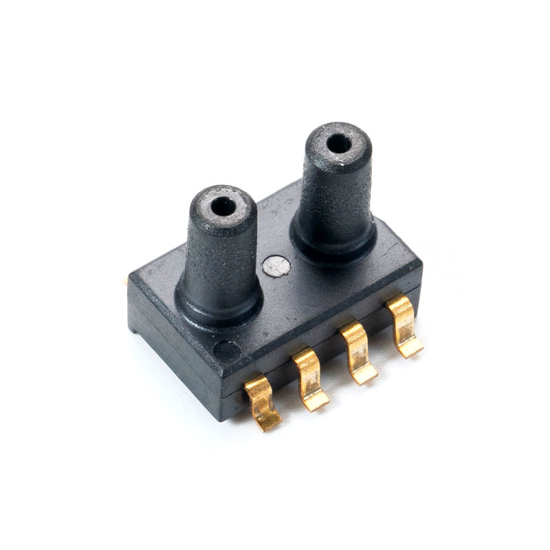
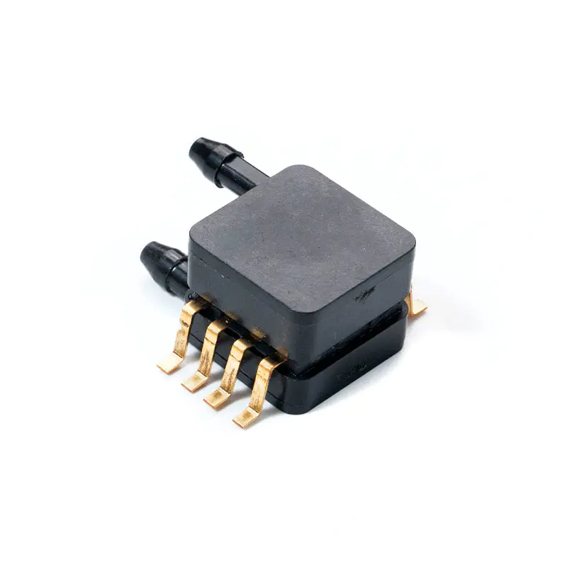
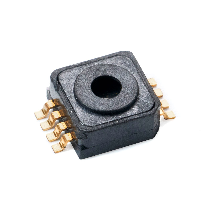
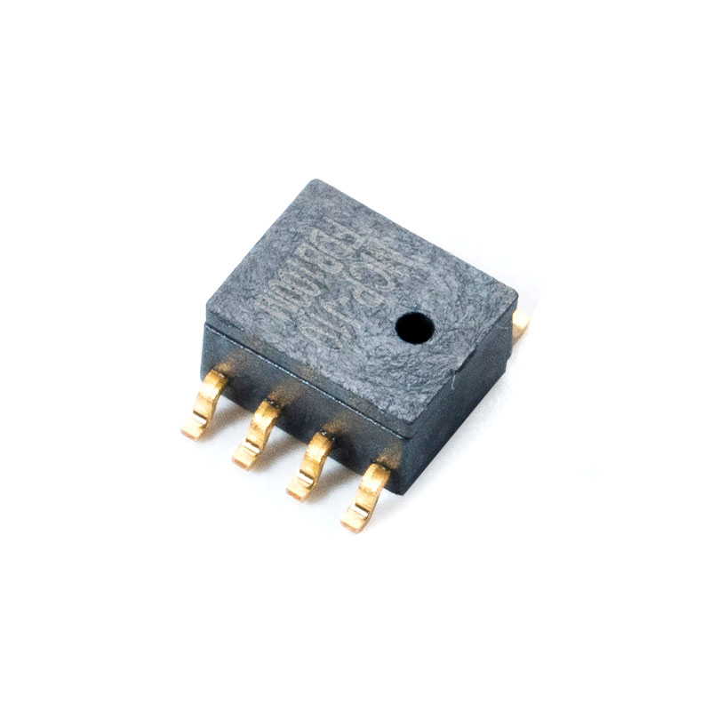
MemsTech's medium pressure sensor portfolio spans a broad range of pressure ranges (from sub-bar to 100 bar), output types (analog, I²C, SPI, 4–20 mA), and packaging configurations (SMD, through-hole, DIP, threaded process connection) tailored to three primary market verticals:
- Medical: Sensors engineered for respiratory equipment, sterilization monitoring, infusion systems, and diagnostic instrumentation—manufactured under ISO 13485 quality management requirements with full calibration traceability.
- Automotive: MEMS pressure sensors meeting AEC-Q100 Grade 1 environmental qualification for manifold pressure, fuel vapor monitoring, brake fluid pressure, and transmission line pressure measurement.
- Consumer Electronics: Compact, ultra-low-power MEMS sensors for smart home devices, portable weather instruments, wearable health monitors, and IoT edge nodes requiring the smallest possible footprint and minimum current draw.
5.3 Why B2B Buyers and Wholesale Partners Choose MemsTech
- In-house R&D capability: MemsTech's engineering team handles the complete development cycle from MEMS die design through ASIC programming and module-level calibration, enabling rapid customization for OEM and ODM customer requirements.
- Scientific production management: ISO-controlled manufacturing lines incorporate statistical process control (SPC) and automated optical inspection (AOI) at each critical process step, ensuring consistent yield and outgoing quality at production scale.
- Rigorous packaging and testing: Every medium pressure sensor undergoes full-range pressure calibration, temperature compensation verification, and functional electrical testing before shipment. Optional 100% HTOL (High-Temperature Operating Life) screening is available for automotive and medical customers requiring enhanced reliability assurance.
- Competitive pricing: Vertical integration—from wafer-level MEMS fabrication through final module assembly—combined with high-volume production efficiency allows MemsTech to deliver high-performance, cost-effective sensing solutions that meaningfully reduce system BOM cost without compromising long-term field reliability.
6. Frequently Asked Questions (FAQ)
Q1: What pressure range is considered "medium" for pressure sensors?
The term "medium pressure" is broadly defined across the industry as the range from approximately 1 bar (100 kPa) to 100 bar (10 MPa). This range encompasses the majority of industrial fluid power, water distribution, HVAC, and automotive applications. Below 1 bar is classified as low pressure (barometric, respiratory, duct pressure), and above 100 bar is considered high pressure (hydraulic presses, subsea, high-pressure testing). Within the medium range, sub-categories of 1–10 bar, 10–40 bar, and 40–100 bar represent meaningfully different design and material requirements for the medium pressure sensor.
Q2: How is a medium pressure sensor different from a high pressure sensor?
The core difference in a medium pressure sensor vs high pressure sensor comparison lies in the mechanical design of the sensing element. A medium pressure sensor uses a thinner diaphragm (optimized for sensitivity in the 1–100 bar range), lighter process connections (G1/4, NPT 1/4), and standard wetted materials such as 316L stainless steel or ceramic. A high pressure sensor requires a substantially thicker diaphragm, heavier-walled pressure body (often forged Inconel or 17-4PH stainless), and specialized high-pressure fittings (HP cone and thread, autoclave connectors). Beyond mechanical differences, high pressure sensors typically have lower sensitivity (wider full-scale spread) and higher unit costs due to manufacturing complexity and material requirements.
Q3: Can a medium pressure sensor be used in water treatment and distribution systems?
Yes, and medium pressure sensors for water systems are among the highest-volume applications for this sensor class. Municipal water distribution networks, booster pump stations, irrigation controllers, and wastewater pumping systems all operate within the medium pressure range (typically 2–16 bar). For potable water contact, the sensor's wetted materials must comply with NSF/ANSI 61 certification requirements. For outdoor and buried installations, IP67 or IP68 ingress protection is required. For SCADA integration over long cable distances, 4–20 mA output with optional HART communication protocol is the industry standard. Always verify that the sensor's proof pressure rating exceeds the maximum credible water hammer event pressure in the specific system.
Q4: What is the best approach to using a low cost medium pressure sensor with Arduino?
For a low cost medium pressure sensor Arduino application, the recommended approach is to select a MEMS-based sensor with a native I²C or SPI digital output, a supply voltage compatible with your Arduino variant (3.3 V for ARM-based boards, or a 5 V-tolerant version for Arduino Uno), and confirmed open-source library support. Before writing any firmware, verify the sensor's I²C address and confirm it does not conflict with other devices on your bus. For pressure measurement in liquids, use a sensor with an appropriate process port (barbed or threaded fitting) rather than a bare die. For highest accuracy, perform a two-point calibration (at atmospheric pressure and at a known reference pressure) to correct for unit-to-unit offset variation typical of low-cost MEMS devices.
Q5: How long does a medium pressure sensor last in continuous industrial use?
A well-selected and properly installed medium pressure sensor for industrial automation can achieve a service life of 5–15 years in continuous operation. Key factors affecting longevity include: (1) Pressure cycling fatigue—sensors exposed to high-frequency pressure cycling (e.g., pneumatic systems cycling 10+ times per minute) accumulate diaphragm fatigue cycles; always check the manufacturer's rated cycle life (typically 10 million to 100 million cycles for quality MEMS sensors); (2) Media compatibility—chemical attack on wetted materials is a leading cause of premature failure; (3) Temperature extremes—operating near or beyond the compensated temperature range accelerates seal degradation and ASIC drift; (4) Vibration—in high-vibration environments (compressors, pumps, engines), use sensors with vibration ratings per IEC 60068-2-6 and consider remote mounting with capillary tubing to isolate the sensor from mechanical vibration sources.
Conclusion
The medium pressure sensor is an indispensable component across a broad spectrum of engineering applications—from municipal water infrastructure and industrial hydraulics to automotive powertrain management and IoT-connected embedded systems. Selecting the right sensor requires a systematic evaluation of pressure range, accuracy, media compatibility, output interface, and environmental ratings rather than defaulting to the lowest-cost option.
Whether you need a medium pressure sensor for water systems, a ruggedized medium pressure sensor for industrial automation, or a low cost medium pressure sensor Arduino-compatible solution for prototyping, the core engineering principles of proper range selection, proof pressure margin, and interface matching remain constant. Understanding how a medium pressure sensor vs high pressure sensor differs in design and application ensures that your system is neither over-engineered nor underspecified—delivering the optimal balance of performance, reliability, and cost.
References
- Fraden, J. (2016). Handbook of Modern Sensors: Physics, Designs, and Applications (5th ed.). Springer. https://doi.org/10.1007/978-3-319-19303-8
- International Electrotechnical Commission. (2005). IEC 60770-1: Transmitters for use in industrial-process control systems – Methods for performance evaluation. IEC.
- International Organization for Standardization. (2016). ISO 13485:2016 – Medical devices – Quality management systems – Requirements for regulatory purposes. ISO. https://www.iso.org/standard/59752.html
- Automotive Electronics Council. (2014). AEC-Q100 Rev-H: Failure Mechanism Based Stress Test Qualification for Integrated Circuits. AEC.
- European Parliament. (2014). Directive 2014/68/EU on the harmonisation of the laws of the Member States relating to the making available on the market of pressure equipment (PED). Official Journal of the European Union.
- NSF International. (2020). NSF/ANSI Standard 61: Drinking Water System Components – Health Effects. NSF International. https://www.nsf.org/testing/water/nsf-ansi-iso-61
- MEMS & Sensors Industry Group. (2023). MEMS & Sensors Market and Application Report. SEMI. https://www.semi.org/en/communities/msig
- International Electrotechnical Commission. (2007). IEC 60068-2-6: Environmental testing – Part 2-6: Tests – Test Fc: Vibration (sinusoidal). IEC.
Recommended Articles


Mems Tech has specialized in the field of pressure sensors for over 14 years.
-
 [email protected]
-
 +86-18068257393
-
 50-1125 Zhongbang City Garden, No.2008 Taihu East Avenue, Xinwu District, Wuxi City, Jiangsu Province, China
Copyright © 2025 byWuxi Mems Tech Co., Ltd. Rights Reserved.
Custom MEMS Pressure Sensor Manufacturers
