
 English
 Français
 中文简体
中文简体1. Introduction to Next-Generation Industrial Sensing Technology
Industrial manufacturing environments are undergoing a massive transformation driven by automation and the need for real-time, data-driven decisions. At the heart of this transformation is the sensor, a critical component responsible for gathering physical data from the factory floor and translating it into actionable insights. Historically, factories relied heavily on analog sensors to monitor parameters like pressure, temperature, flow, and chemical composition. While these traditional systems served the industry well for decades, they possess inherent vulnerabilities that limit their effectiveness in modern, high-speed, and highly automated production lines.
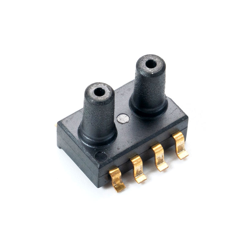
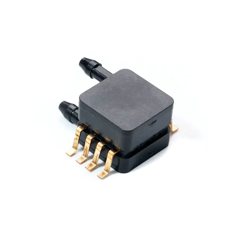
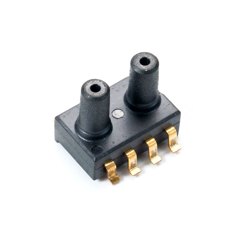
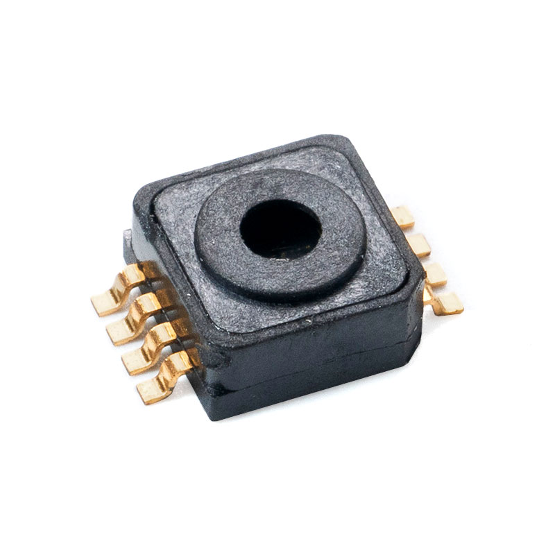
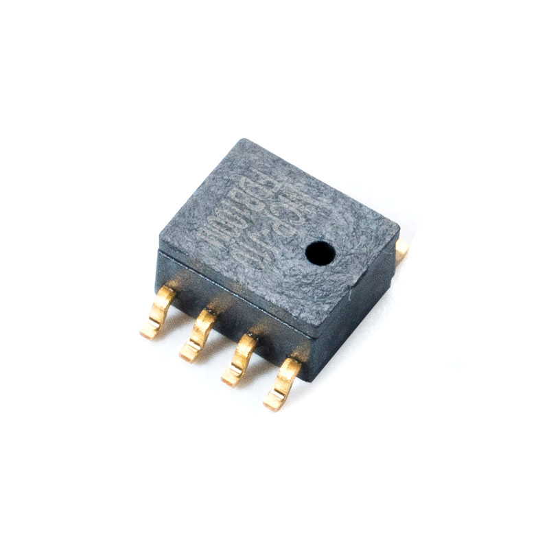
The emergence of advanced digital sensing systems has redefined what engineers can expect from factory floor data collection. The MCP-H21 Digital signal sensor represents a significant leap forward in this domain, integrating high-performance sensing elements directly with on-board digital signal processors. By converting physical phenomena into robust digital packets right at the point of measurement, this sensor addresses the fundamental limitations of signal degradation, electrical noise interference, and calibration drift that plague older analog architectures.
For export-oriented manufacturing operations supplying international markets, integrating reliable digital sensors is no longer optional. Global buyers demand systems that minimize downtime, support remote diagnostics, and integrate seamlessly with programmable logic controllers (PLCs) and supervisory control and data acquisition (SCADA) systems. Understanding the underlying technology of digital signal communication, and how it directly compares to traditional legacy methods, is essential for procurement managers and design engineers aiming to build future-proof machinery.
2. Theoretical Breakdown: Digital Signals vs. Analog Signals
To appreciate the operational advantages of advanced digital sensing devices, it is necessary to examine the physical differences between analog and digital signal transmissions. An analog signal provides a continuous, unbroken wave of voltage or current that directly corresponds to the physical property being measured. For example, a legacy pressure sensor might output a continuous voltage ranging from 0 Volts to 10 Volts, where 0 Volts indicates zero pressure and 10 Volts represents maximum rated capacity.
While straightforward in concept, this continuous mapping means that any alteration to the signal wave during its journey from the factory floor to the control room directly corrupts the data. If electromagnetic interference introduces an extra 0.5 Volts onto the wire, the control system interprets this noise as a genuine change in pressure. This vulnerability necessitates expensive shielded cables and limits the distance over which the signal can travel before becoming unreadable.
In contrast, a digital signal breaks data down into discrete binary units, consisting entirely of ones and zeros represented by distinct voltage thresholds. The sensor samples the physical environment at high frequencies and uses an integrated analog-to-digital converter to format this data into precise numeric values. Because the receiving controller only looks for distinct binary states rather than exact, continuous voltage levels, minor fluctuations in the voltage wave caused by external noise do not change the underlying data value. A binary one remains a one, even if the voltage wave experiences minor distortions along the transmission path.
3. Comprehensive Feature Comparison Matrix
When assessing whether to specify a digital sensor platform or stick with traditional analog devices, evaluating key performance metrics side by side provides absolute clarity. The following table highlights the core operational distinctions between these two generations of industrial sensing technology.
| Operational Parameter | Traditional Analog Sensors (4-20mA / 0-10V) | MCP-H21 Digital Signal Sensor |
|---|---|---|
| Signal Integrity over Distance | High degradation; susceptible to line resistance and voltage drops. | Zero degradation; digital data packets remain intact over long distances. |
| Electromagnetic Noise Immunity | Low; requires heavy cable shielding and careful routing away from motors. | Exceptional; binary logic filters out common factory electrical noise. |
| Calibration and Maintenance | Manual calibration required via potentiometers at the physical sensor site. | Software-defined calibration; remote offset adjustments and configurations. |
| Data Throughput Capability | Single-variable output only (one variable per physical wire pair). | Multi-variable output (primary data, temperature, status, diagnostics). |
| System Integration Overhead | Requires dedicated analog input cards on PLCs, increasing system footprint. | Direct bus connection (RS485/Modbus); links multiple sensors on one line. |
| Diagnostic Availability | Cannot differentiate between a dead sensor, a broken wire, or zero value. | Continuous self-testing with specific error code broadcast capabilities. |
4. Architectural Analysis of the MCP-H21 Infrastructure
The operational superiority of the MCP-H21 architecture stems from its sophisticated internal engineering. Unlike basic sensors that merely house a transducer element, this device incorporates an entire signal processing chain within its compact housing. The physical sensing element converts the environmental variable into a localized micro-signal, which is immediately routed into a high-resolution, low-noise internal amplifier.
Once amplified, the signal enters a dedicated microprocessor core. This core performs real-time mathematical filtering, temperature compensation, and linear adjustments based on factory-calibrated parameters stored in non-volatile memory. By compensating for thermal expansion and cross-sensitivity directly inside the sensor body, the unit guarantees that the digital output values transmitted to the main control system reflect true environmental metrics, completely independent of ambient factory temperatures.
The final stage of the internal architecture is the industrial communication interface. Utilizing an RS485 physical transceiver, the device formats the processed measurement data into standard industrial protocols, such as Modbus RTU. This design enables the sensor to communicate directly with any modern PLC, industrial computer, or IoT gateway without requiring specialized, high-cost analog-to-digital conversion modules in the central control cabinet.
5. Noise Immunity and Signal Integrity in Heavy Industrial Environments
Industrial manufacturing plants are notoriously hostile environments for electrical signals. Heavy machinery, variable frequency drives (VFDs), welding equipment, and high-voltage power lines generate massive amounts of electromagnetic interference (EMI) and radio frequency interference (RFI). When traditional analog sensors are deployed in close proximity to these noise sources, the continuous voltage or current signals traveling along the cables act like long antennas, absorbing the ambient interference.
This induced noise distorts the measurement values reaching the PLC. In high-precision manufacturing, such as semiconductor fabrication, automotive assembly, or chemical processing, even a one percent error in sensor readings can result in defective product batches, ruined materials, or catastrophic equipment failure. To combat this, engineers utilizing analog systems must invest heavily in expensive double-shielded twisted-pair cables, route lines through dedicated grounded metal conduits, and strictly limit the length of cable runs.
Digital signal sensing completely eliminates these engineering bottlenecks. Because digital communication protocols rely on differential voltage signaling across two wires (where the receiver detects the difference in voltage between the lines rather than an absolute voltage against ground), any external noise that impacts the cable affects both wires equally. The receiving controller subtracts the two signals, effectively canceling out the common-mode noise while leaving the digital data packet completely unaffected. This allows the sensor to maintain absolute accuracy over cable runs extending up to several hundred meters, running directly alongside high-voltage power lines without performance degradation.
6. Multi-Variable Data Transmission and Diagnostic Capabilities
A major limitation of traditional analog architectures is their single-channel nature. A standard 4-20 milliamp loop can only communicate a single variable at a time. If a sensor needs to monitor both primary physical pressure and internal sensor temperature, the manufacturer must install two separate sensing elements, run two independent sets of wires, and purchase two distinct analog input channels on the PLC.
Digital architecture overcomes this limitation by utilizing packet-based serial data networks. Through a single physical connection, the digital platform can bundle multiple data points into a single transmission frame. When the PLC queries the device, the sensor responds with a rich data set that includes the primary process value, secondary environmental parameters, internal diagnostic flags, and device serial numbers.
This multi-variable transmission capability enables an entirely new paradigm of industrial maintenance: predictive diagnostics. In analog systems, if a wire breaks or a sensor element burns out, the circuit simply drops to zero volts or zero milliamps. The control system cannot determine whether the sensor is reporting a valid zero reading or if the entire system has failed, leading to delayed fault detection. A digital sensor continuously evaluates its own internal health. If an anomaly occurs, it transmits an explicit error code packet to the PLC, allowing maintenance teams to instantly pinpoint the exact nature of the fault, whether it is an internal element failure, an over-range condition, or a power supply variance.
7. Scaling and Cost-Efficiency in Multi-Sensor Networks
As industrial operations expand, the number of monitoring points across a factory floor increases exponentially. In an analog-reliant infrastructure, scaling up a facility requires a massive capital investment. Every single analog sensor added to the line demands a dedicated cable run back to the central control panel, a dedicated slot on an analog input module, and extensive manual wiring work. Analog input modules for PLCs are notoriously expensive components, often costing significantly more than digital input alternatives.
Furthermore, long analog cable runs introduce cumulative loop resistance. Engineers must carefully calculate wire lengths, voltage drops, and power supply capabilities to ensure the sensor receives adequate operating power while maintaining signal precision. This complex balancing act increases engineering design hours and raises the probability of installation errors during commissioning.
Deploying digital units utilizing bus-based communication protocols radically simplifies network expansion. Devices running on an RS485 multi-drop network can be configured in a daisy-chain topology. This means a single master cable can exit the control cabinet, run along the factory production line, and connect to multiple sensors in sequence. Each device is assigned a unique digital address on the network.
The control system communicates with each sensor individually over the same pair of wires, radically reducing the volume of cabling required, eliminating the need for expensive multi-channel analog cards, and reducing installation labor costs by up to seventy percent.
8. Integration Protocol Standards and Software Integration
Modern industrial systems thrive on standardization. When choosing components for export-grade machinery, using globally recognized communication protocols ensures compatibility with various control systems used by international buyers. The digital sensor utilizes standard serial communication parameters, making it natively compatible with the widely adopted Modbus RTU protocol.
This standardized digital structure allows for rapid software integration. Instead of spending hours calibrating analog input scales within the PLC code (mapping a 4mA current to 0 bar and 20mA to 10 bar, and then adjusting for offset errors), programmers simply input the modbus register address assigned to the sensor's measurement value. The PLC reads the exact digital value directly from the sensor memory, ensuring absolute data fidelity between what the sensor measures and what the PLC processes.
Moreover, software integration enables dynamic parameter modification. If a production line switches from processing a high-density material to a low-density material, the control system can automatically broadcast new configuration parameters, filtering coefficients, or sensitivity thresholds to the digital sensors on the fly. This eliminates the manual recalibration downtime associated with legacy equipment, allowing factories to achieve true agile manufacturing.
9. Real-World Applications and Global Compliance
The advantages of digital signal sensors manifest clearly across diverse industrial applications, particularly those requiring extreme precision and long-term stability under harsh conditions. In the field of environmental monitoring and industrial wastewater treatment, sensors are subjected to highly corrosive atmospheres and shifting ambient temperatures. Traditional analog setups drift quickly under these conditions, requiring frequent on-site recalibration by specialized technicians. Utilizing the internal temperature compensation of the digital sensor ensures stable, accurate tracking over extended lifespans, minimizing field maintenance.
In automated assembly lines and automotive manufacturing, where robotic arms move at high speeds and generate high levels of kinetic and electromagnetic noise, digital sensors provide the necessary reliability to avoid false triggers or missed steps. The robust signal delivery ensures that automated control loops receive precise feedback, directly translating to higher yield rates and superior product finish quality.
For manufacturing exporters sending machinery into the European, North American, or Asian markets, utilizing advanced digital sensors simplifies regulatory compliance. International standards increasingly emphasize machine safety, energy efficiency, and detailed data logging for quality assurance. The integrated self-diagnostics and high-resolution data streams provided by digital architectures enable exporters to build machines that fully satisfy global regulatory frameworks, providing a clear competitive advantage in the international market.
10. Long-Term Maintenance and Calibration Life Cycles
The total cost of ownership for industrial equipment is heavily influenced by ongoing maintenance and calibration requirements. All sensors drift over time due to mechanical stress, thermal aging, and material degradation of the sensing elements. With traditional analog equipment, rectifying this drift is a labor-intensive manual process. A maintenance technician must travel to the sensor location with a reference calibration source, open the sensor enclosure, and manually turn microscopic potentiometers with a screwdriver until the analog output matches the reference value. This process is susceptible to human error and can introduce moisture or contaminants into the sensor housing during open-field adjustments.
Transitioning to a digital sensor ecosystem shifts calibration into the digital domain. Because the internal microprocessor manages all scaling and calibration parameters, adjustments can be executed purely via software commands over the communication network. Technicians can perform remote digital zeroing and span adjustments from the comfort of the central control room, using software interfaces to input calibration offsets directly into the non-volatile memory of the sensor.
Further, because digital sensors can monitor their own internal environmental exposure history (such as logging maximum temperature spikes or over-pressure events), the device can proactively inform the control system when a physical calibration check is actually necessary. This transitions the facility from a rigid, schedule-based maintenance strategy to a highly efficient condition-based maintenance model, driving down operating costs and maximizing production uptime.
11. Conclusion
The transition from traditional analog signaling to advanced digital signal processing represents a cornerstone evolution in the industrial manufacturing sector. The limitations of legacy systems—ranging from high susceptibility to electromagnetic noise and severe signal attenuation over distance, to high wiring complexities and a total lack of internal diagnostic insight—create substantial barriers for modern, highly automated production environments.
Devices like the digital sensor address these critical vulnerabilities by delivering robust noise immunity, multi-variable data streams, simplified daisy-chain networking, and comprehensive self-monitoring capabilities. For manufacturing exporters aiming to compete on a global scale, incorporating digital sensor architectures ensures that machinery meets international performance expectations, reduces commissioning timelines, and provides end-users with unparalleled reliability and operational intelligence.