

 English
 Français
 中文简体
Reconciling MemsTech's 0.2% Accuracy Claim With the MCPh10 ±1.5% VFSS Spec
Date:2026-11-12
Content
- 1 The short answer: 0.2% and ±1.5% VFSS measure different things
- 2 Where each number actually lives
- 3 Three readings of the 0.2% claim, and how to test each
- 4 A five-step reconciliation protocol for buyers
- 5 What fills the gap: the error budget behind ±1.5% VFSS
- 6 Match the grade to the loop before you argue about decimals
- 7 What to put in the purchase order
- 8 Practical questions buyers raise
Two numbers sit on the same desk at the design review: MemsTech's corporate materials describe accuracy up to 0.2%, and the MCPh10 datasheet specifies ±1.5% VFSS. On a 100 kPa gauge range that is ±0.2 kPa against ±1.5 kPa, a factor of 7.5, and the difference can decide whether a dosing loop or an altitude-compensation routine meets its budget. The gap is real, but it is not a contradiction. The two figures describe different quantities measured under different conditions, and a buyer who separates them can reconcile both in a single afternoon of specification work.
The short answer: 0.2% and ±1.5% VFSS measure different things
The 0.2% figure is a single-condition value for linearity or repeatability, while ±1.5% VFSS is a span-referenced total error band across the compensated temperature range. Both can be true on the same part, and neither one cancels the other.
VFSS, full-scale span voltage, is the algebraic difference between the sensor output at rated full-scale pressure and its output at zero pressure. An error quoted in % VFSS is a fraction of that span, not of the instantaneous reading: on a part with a 100 mV span, ±1.5% VFSS equals ±1.5 mV at every point of the range.
That distinction matters because a span-referenced number does not shrink at low pressure. At 10% of range the same ±1.5% VFSS is still ±1.5 kPa on a 100 kPa part, which is 15% of the reading. Reference accuracy under IEC 61298-2, and the definitions used across the IEC 60770 series for process transmitters, follow the same logic: a figure only means something when the reference conditions, the fitting method and the temperature band travel with it.
| Figure | What it quantifies | Conditions that decide it |
| 0.2% (corporate claim) | Non-linearity or repeatability of a selected grade | Single ambient temperature near 25 °C, reference supply, static pressure, stated fitting method |
| ±1.5% VFSS (datasheet) | Combined linearity, hysteresis, repeatability, offset and span tolerance, thermal drift | Full compensated band, after per-unit zero and span calibration |
| Per-unit calibration | Zero and span trim against a reference standard | One temperature point, one pressure cycle, recorded on the calibration sheet |
| Long-term stability | Drift of zero and span over time, quoted as % VFSS per year | Static pressure, constant temperature, no thermal or pressure cycling |
Where each number actually lives
The 0.2% claim sits inside a component-capability statement, and the ±1.5% VFSS line sits inside a guaranteed limit that includes thermal and calibration terms. Reading them as the same measurement is the single most common sourcing error on this part family.
- Linearity of the best-performing grade at one temperature
- Repeatability at a fixed pressure point over a short cycle count
- Bench data from a trimmed sample, not a lot average
- Excludes thermal drift, mounting stress and long-term shift
- Non-linearity across the entire rated pressure range
- Hysteresis and repeatability from repeated pressure cycles
- Zero and span tolerance after per-unit calibration
- Thermal zero and span drift across the compensated band
A buyer who enters 0.2% into a spreadsheet as if it were a total error band understates the real error by a factor of 7.5 at full scale and by far more at 10% of range. A buyer who enters ±1.5% VFSS and then designs a 0.5% loop over-specifies the part and pays for accuracy the application never uses. The MEMS pressure sensor technology guide covers how the diaphragm, bridge and compensation network interact to produce each term in that band.
Three readings of the 0.2% claim, and how to test each
Ask the supplier which of three readings is intended; each one is testable and each one carries a different practical meaning for your design.
- Best-grade non-linearity at 25 °C. Terminal-based, best-fit straight line and least-squares fits on the same bowed output curve can differ by a factor of two, so the fitting method alone can move a part from 0.4% to 0.2%. Test: request the raw linearity scan plus the method used to derive the reference line.
- A selected premium bin. MemsTech runs in-house encapsulation, temperature compensation and calibration in a 2,000 square metre facility with a stated capacity of 60 million units per year, so a hand-selected subset can genuinely hold 0.2% while the catalog part keeps the wider guaranteed band. Test: ask for the bin definition, the selection criteria and the lot rejection rate behind it.
- Repeatability at a single point, not full-range accuracy. A spread figure at 50% of span over five cycles says nothing about endpoints or about drift near zero. Test: run five up-and-down cycles at 0, 25, 50, 75 and 100% of range and compare the spread at each point separately.
A five-step reconciliation protocol for buyers
Five steps convert the two competing numbers into one defensible acceptance criterion, and the whole sequence takes roughly one working week once the supplier responds.
- Get the test conditions in writing. Ask for ambient temperature, supply voltage or current, pressure medium, mounting torque and warm-up time for every quoted figure. A number without those five items is marketing text, not a specification.
- Convert everything to engineering units. Multiply each % VFSS term by your actual span. On 100 kPa span, ±1.5% VFSS is ±1.5 kPa; on 10 kPa span, the same percentage becomes ±0.15 kPa and the sensor may now be acceptable.
- Rebuild the error budget with a declared summation. Guaranteed limits are usually summed arithmetically, while a root-sum-square of independent terms typically lands between 0.7% and 0.9% for a band guaranteed at 1.5%. Decide which method your quality system accepts before you compare numbers with the vendor.
- Qualify 30 units across three temperatures. Thirty units at -20, 25 and 60 °C, five pressures up and down, produces 900 readings and supports a lot-level maximum rather than a single-unit average. Sample across at least three production lots.
- Write the acceptance number into the purchase order. Specify total error band, compensated range, calibration certificate and lot traceability. A headline percentage in a product brochure is not a purchase specification.
What fills the gap: the error budget behind ±1.5% VFSS
Six span-referenced terms, not one, produce a ±1.5% VFSS band, and linearity is usually the smallest contributor in the allocation. Zero offset and thermal drift together account for roughly half the total.
The allocation above is an illustrative pattern that sums arithmetically to 1.50%, not a datasheet extract; request the manufacturer's own budget before quoting a number internally. The design lesson holds either way. Because offset and thermal terms dominate, the money in a ±1.5% VFSS part goes into calibration and temperature compensation, which is exactly the per-unit zero and span trim, temperature drift testing and long-term stability evaluation MemsTech describes in its quality process.
Reconciled conclusion: 0.2% is a component capability statement, and ±1.5% VFSS is the guaranteed limit your system will actually see. Design to the second, and ask the supplier to prove the first with raw data.
Match the grade to the loop before you argue about decimals
Choose the part by the error your loop can absorb, not by the smallest percentage on the page; a ±1.5% VFSS part is the correct choice whenever the surrounding signal chain already consumes 1% or more of the budget.
A gauge pressure sensor feeding a 0–100 kPa infusion line usually carries a system budget of ±2% to ±3% of span once tubing compliance, ADC resolution and pump dynamics are counted. At that budget the ±1.5% VFSS band leaves usable margin, and the 0.2% claim cannot be verified at system level in any case. Start from the gauge pressure sensor range and confirm the compensated band before you shortlist.
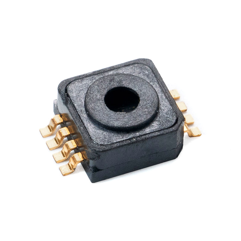
 MCP-H10 Gauge Pressure Sensor SeriesSOP-packaged MEMS gauge sensor with integrated amplification and temperature compensation, offering a 1.5% VFSS accuracy band for medical and consumer pressure designs.View Product →
Medical assemblies deserve a separate check because accuracy interacts with sterilization and connector geometry. Reviewing the part inside its intended application page is faster than reading three datasheets side by side, since the package and pressure-port constraints are already filtered.
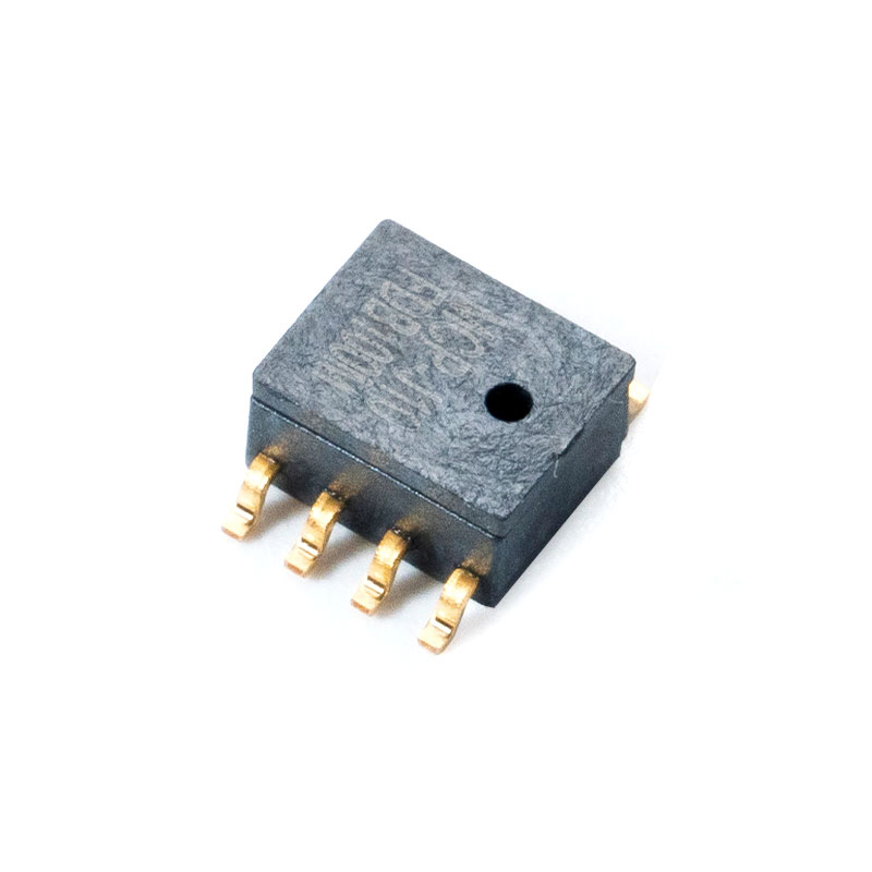
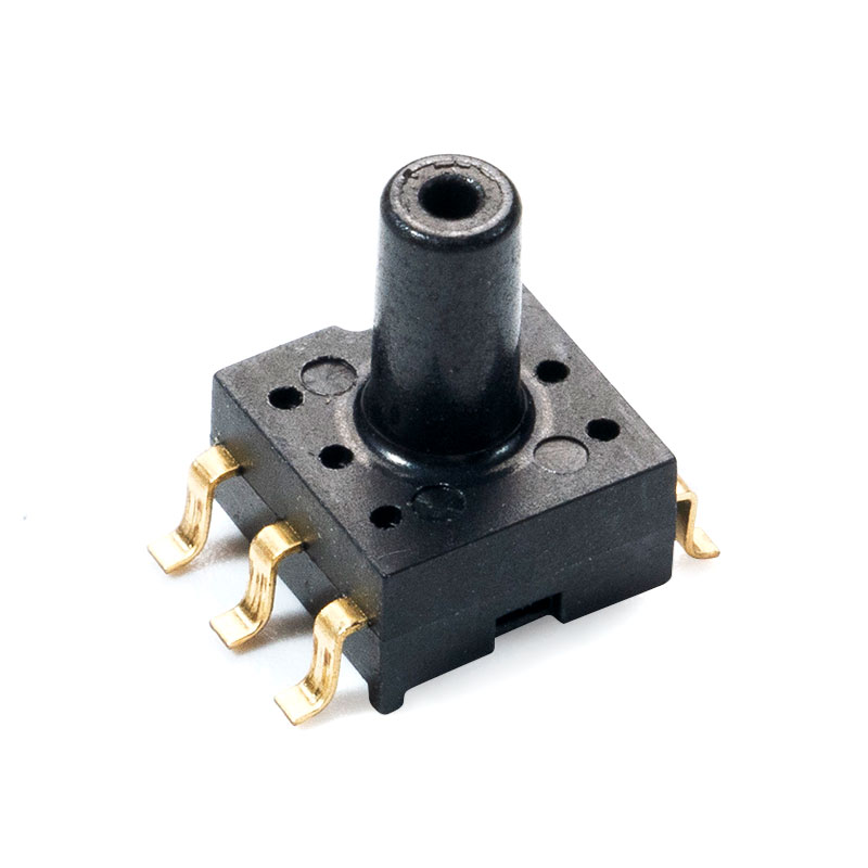 MCP-H10 and MCP-H11 Medical Pressure SensorsSOP surface-mount sensors pairing analog MCP-H10 and I2C digital MCP-H11 options with temperature compensation for medical pressure assemblies.View Product →
Board-level constraints decide the rest. A surface-mount body keeps the pressure port close to the converter and shortens the analog trace, which reduces pickup on a millivolt-level span output. That electrical detail often matters more than the gap between 0.2% and 1.5%, because 2 mV of coupled noise on a 100 mV span is already 2% of reading.
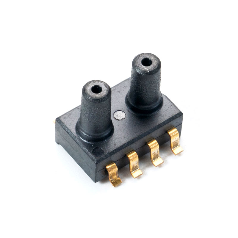
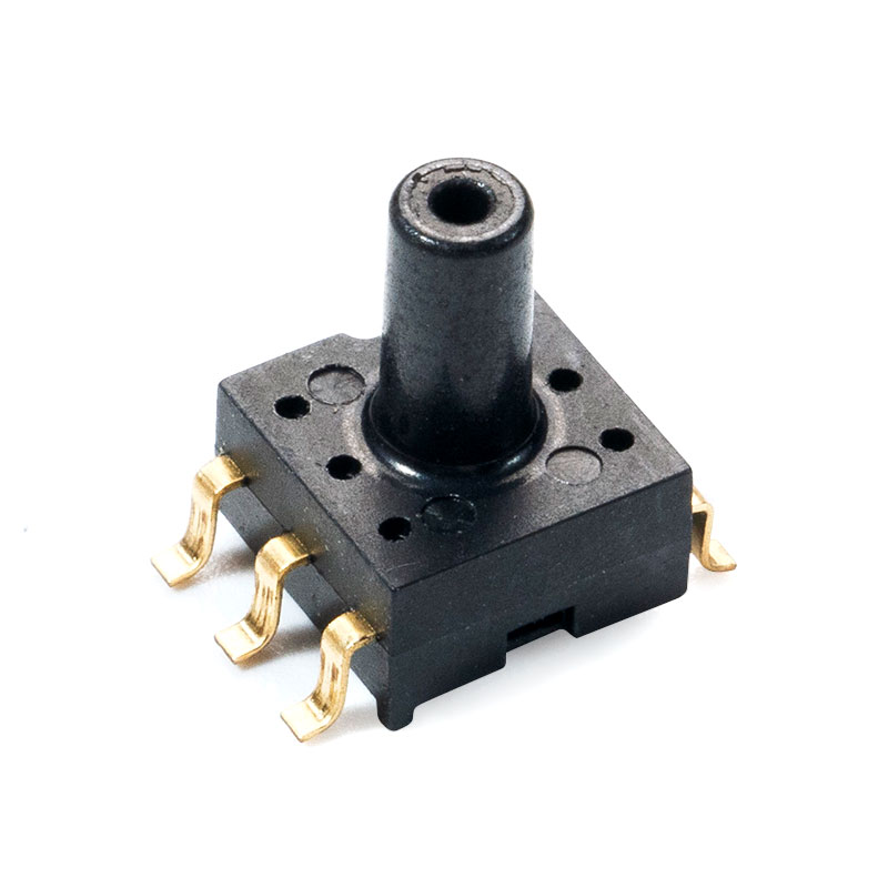 MCP-H10 Surface-Mount Pressure Sensor VariantsSOP pressure sensor series with customizable analog output and many gauge or differential ranges, useful when board-level package and port constraints drive selection.View Product →
What to put in the purchase order
Four clauses convert a reconciled specification into something a supplier can be held to, and each one is checkable at goods-in inspection.
- Total error band: maximum ±1.5% VFSS over the stated compensated range, explicitly including linearity, hysteresis, repeatability, zero offset, span tolerance and thermal drift.
- Calibration record: zero and span trim data per unit or per lot, with the reference standard identified and traceable.
- Qualification data: 30-unit sample results at three temperatures and five pressures in both directions, reported as maxima rather than averages.
- Change control: written notice before any die, package or compensation-network change, followed by requalification against the same acceptance number.
Add a stability clause as well, expressed as % VFSS per year over a defined 12-month period at constant temperature. Stability is the one term that quietly erodes a calibration in the field, and it is rarely covered by the headline accuracy claim.
Practical questions buyers raise
Is the 0.2% claim misleading if the datasheet says ±1.5% VFSS?
No, provided the claim is qualified by test conditions. Reference accuracy measured under IEC 61298-2 style conditions, at a single ambient temperature and with a declared fitting method, is a legitimate capability statement. If a supplier cannot produce the temperature, sample size and fitting method behind a 0.2% figure, treat it as marketing text and hold the ±1.5% VFSS line as the contract value.
Which figure belongs in my error budget?
Use ±1.5% VFSS for the guaranteed analysis and reserve the tighter figure for a 25 °C nominal case that the supplier supports in writing. At 10% of range the span-referenced band still costs ±1.5 kPa on a 100 kPa part, so budget in absolute pressure units rather than in percentages.
How many samples prove the band before production release?
Thirty units is the working minimum: 30 units multiplied by 3 temperatures, 5 pressures and 2 sweep directions gives 900 readings, enough to state a lot-level maximum instead of an average. Draw the sample from at least three production lots so lot-to-lot calibration spread appears in the data.
Does manufacturing scale change the accuracy answer?
No. A 2,000 square metre facility and a stated 60 million units per year describe capacity and process control, not accuracy. Accuracy is fixed by the calibration standard, the reference conditions and the per-lot certificate, so ask for the certificate and the raw qualification data rather than the capacity figure.

Mems Tech has specialized in the field of pressure sensors for over 14 years.
-
 [email protected]
-
 +86-18068257393
-
 50-1125 Zhongbang City Garden, No.2008 Taihu East Avenue, Xinwu District, Wuxi City, Jiangsu Province, China
Copyright © 2025 byWuxi Mems Tech Co., Ltd. Rights Reserved.
Custom MEMS Pressure Sensor Manufacturers
