

 English
 Français
 中文简体
中文简体Medical Pressure Sensors: Matching MEMS Output and Packaging to Clinical Devices
Date:2026-09-17
Content
- 1 What Defines a Medical Pressure Sensor for Clinical Use?
- 2 Medical Pressure Sensor Accuracy: Limits for Patient-Critical Measurements
- 3 Analog or Digital Output: Signal Chain and Interface Fit
- 4 Packaging and Port Configuration: Assembly Risk in the Field
- 5 Calibration and Batch Consistency in Medical Pressure Sensors
- 6 A Cross-Reference Table for Medical Device Teams
- 7 Frequently Asked Questions
Every infusion pump, ventilator, and non-invasive blood pressure monitor relies on medical pressure sensors that hold their calibration through years of clinical service. When you specify one for a patient-contact device, three decisions determine whether the product passes validation: accuracy class, output format, and packaging. Choose those correctly and the sensor becomes a quiet component; choose poorly and it turns into the most expensive field failure in your bill of materials.
What Defines a Medical Pressure Sensor for Clinical Use?
A medical-grade MEMS pressure sensor is not defined by a single certification but by stability specification, material compatibility, and unit-level calibration.
A MEMS pressure sensor is a micro-electromechanical device that converts pressure into an electrical signal through a diaphragm that flexes under applied pressure. A piezoresistive element inside the diaphragm measures that deflection. Capacitive designs exist, but piezoresistive MEMS pressure sensors dominate medical instruments because they offer a stable DC response, low hysteresis, and a mature calibration process.
Full-scale span (FSS) is the difference between the output signal at minimum and maximum rated pressure. Accuracy is the maximum deviation from the ideal output line, expressed in percent of FSS.
The critical specification is accuracy. A 1-percent-FSS sensor on a 0-300 mmHg infusion line is accurate to within 6 mmHg. That margin matters when the alarm threshold sits at 30 mmHg. The second parameter is medium isolation: fluid-contact sensors need a protective gel or stainless-steel barrier so the diaphragm does not touch saline, blood, or medication.
Medical Pressure Sensor Accuracy: Limits for Patient-Critical Measurements
For clinical devices, practical accuracy targets sit between 0.5 percent and 1 percent of full-scale span, and every unit should ship with individual calibration data.
Device engineers often specify sensors with 1.0 percent FSS accuracy and then struggle when the system fails tolerance at elevated body temperatures. The cause is usually thermal drift, not base accuracy. A sensor calibrated at 23 degrees C can drift by several percent of FSS when the device warms to 37 degrees C during use, unless the supplier applies temperature compensation at the factory.
Thermal drift, not base accuracy, is what pushes a nominally correct sensor outside its alarm margin.
| Application | Pressure Range | Base Accuracy | Allowed Drift 0-50 C |
| Infusion pump | 0-6 psi / 41 kPa | +/-1% FSS | +/-1.5% FSS |
| Ventilator | 0-70 cmH2O / 7 kPa | +/-0.5% FSS | +/-1% FSS |
| Patient monitor | 0-300 mmHg / 40 kPa | +/-1% FSS | +/-2% FSS |
| Dialysis fluid circuit | 0-500 mmHg / 66 kPa | +/-1% FSS | +/-1.5% FSS |
| Wearable diagnostic | 0-20 kPa | +/-1% FSS | +/-2% FSS |
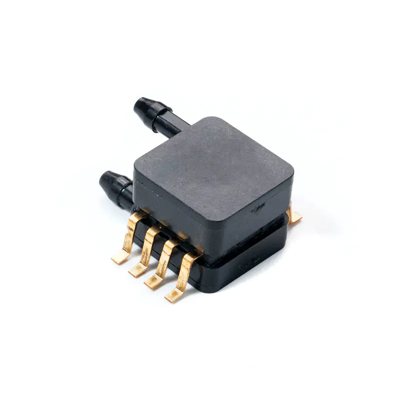
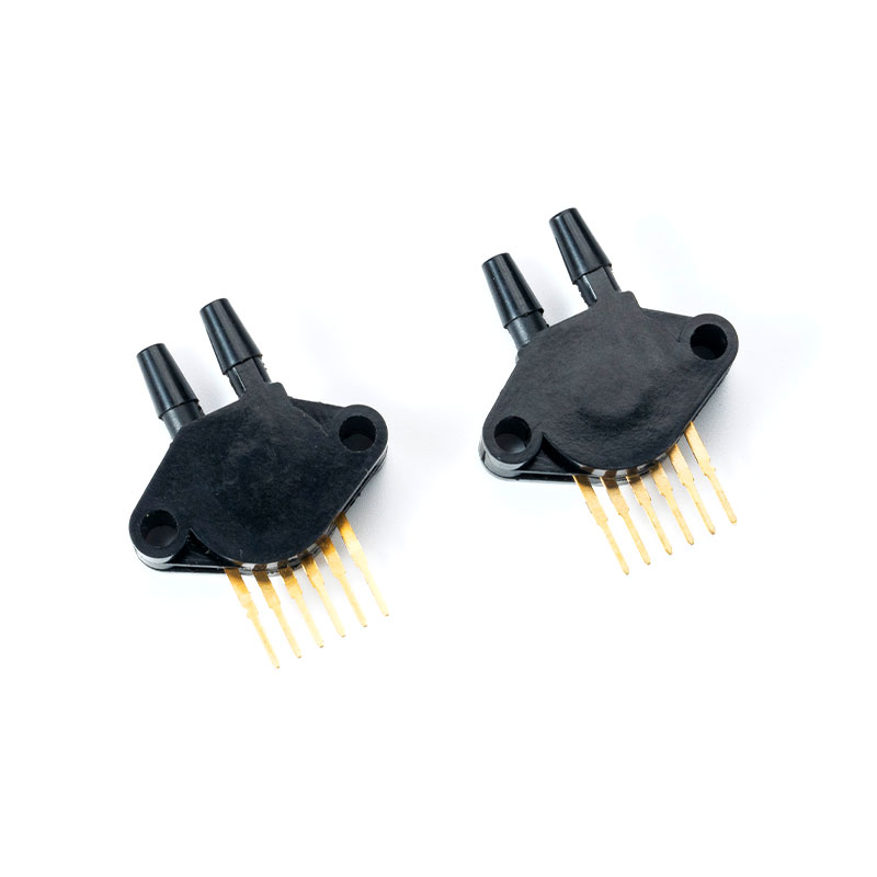 MCP5XXXDP Series Pressure Sensor with Temperature Compensation for Medical ApplicationsThis silicon piezoresistive transducer offers analog output and is temperature compensated over +10 to +60°C, making it reliable across operating ranges. It suits medical equipment like ventilators and monitors where thermal drift matters.View Product →
Because thermal drift dominates the error budget, ask the supplier for a temperature compensation specification, not just a room-temperature accuracy number. Compensation is usually done with a 2-point or 3-point correction across 0-50 degrees C. The result should be a sensor that holds its output inside the stated accuracy band over the entire production temperature range, not just at 23 degrees C.
Analog or Digital Output: Signal Chain and Interface Fit
Choose analog output when your converter and amplifier chain are already fixed; choose digital when you need calibrated readings over I2C or SPI and want to avoid per-unit offset trimming.
Analog sensors output a ratiometric voltage that scales with supply and pressure. They are simple, inexpensive, and comfortable for the design team. Digital sensors, on the other hand, contain an on-chip ADC, a temperature sensor, and a set of calibration coefficients. They return fully compensated pressure readings over a serial interface.
Analog output
- Near-universal compatibility with MCU ADC inputs
- Lower sensor cost, simpler supply chain
- Needs external signal conditioning
- Offset drift must be handled in firmware
Digital output
- On-chip temperature compensation
- Direct I2C or SPI reading
- No per-unit trimming on your line
- Higher unit cost, more complex timing
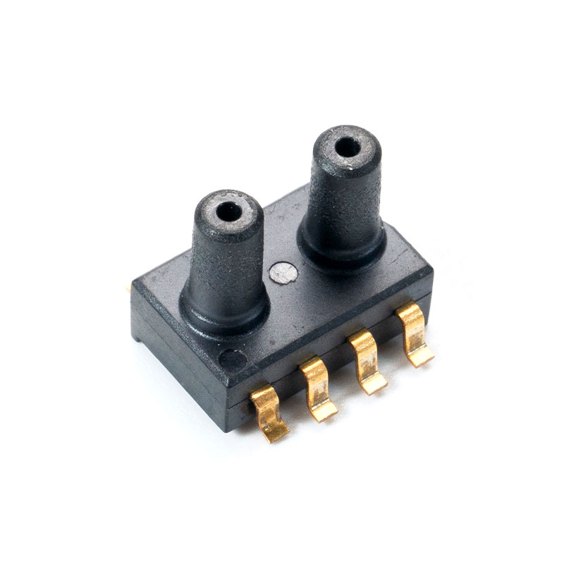
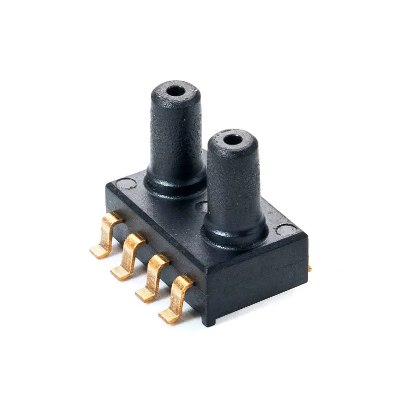 MCP-H20 and MCP-H21 Pressure Sensors for Medical DevicesThese SOP pressure sensors come in analog and digital versions. The H21 provides 24-bit digital pressure and temperature via I²C, while H20 gives analog output. Both are designed for consumer and medical electronics, with options for various pressure ranges.View Product →
Medical devices with limited PCB space and a ready MCU usually fit a digital sensor. If your instrument already has a precision ADC, an analog sensor reduces cost without compromising accuracy.
Packaging and Port Configuration: Assembly Risk in the Field
The package, and not the silicon, is the most common source of field failures in medical pressure sensors.
A MEMS pressure sensor dies quickly when the diaphragm is contaminated, when the port leaks, or when mechanical stress is transmitted to the package. Three packaging decisions affect your assembly yield.
- Package footprint: SOP (surface mount) is smaller and suited to PCB integration; DIP/SIP (direct plug) allows bulkhead mounting and easier service.
- Port type: Tube ports fit flexible silicone tubing; nipple ports connect to a pneumatic line; PCB mount ports are used where the sensor sits directly on a sealed cavity.
- Gel coating: A silicone gel layer on the diaphragm isolates the silicon from fluid circuits, enabling liquid measurement in dialysate and blood pressure lines.
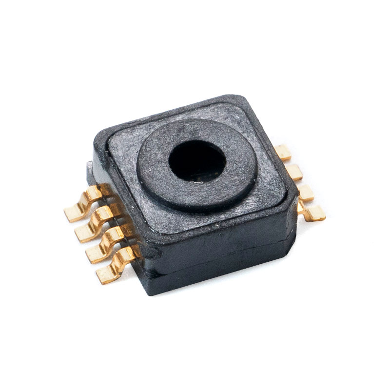
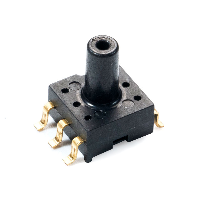 MCP-H10 and MCP-H11 Pressure Sensors with Nozzle for Medical UseThese compact SOP sensors integrate amplification and compensation. H10 outputs analog voltage from 0.5V to 4.5V, while H11 offers 24-bit digital pressure and temperature. They are suitable for blood pressure monitors and other medical devices, with wide pressure ranges.View Product →
If the sensor is used in a wet environment, the gel must be specified with a wall thickness and cure profile, because gel thickness directly affects response time and thermal lag.
Calibration and Batch Consistency in Medical Pressure Sensors
Every sensor must be zeroed and spanned at the supplier's line before it leaves the factory, and sample testing is not acceptable for patient-contact devices.
At MemsTech (Wuxi Mems Tech Co., Ltd.), the calibration process is automated, with each unit receiving zero and full-scale adjustment plus temperature compensation. The output is a batch consistency that shows up as a tight distribution of offsets across the reel, which is what a quality engineer wants to see when a production lot arrives.
Thermal error after compensation
Typical error in percent of full scale over the 0-50 degrees C band, with and without compensation.
The stability rating is usually reported as FSS drift per year. Look for a number below 0.1 percent per year for the ranges used in patient monitoring, because the sensor will be validated once and then trusted during its service life.
A Cross-Reference Table for Medical Device Teams
Use this table to translate measurement requirements into a pressure sensor configuration.
Rather than memorizing part numbers, compare the decision factors that actually change your bill of materials and your risk profile.
| Factor | Ask Your Supplier | Why It Matters |
| Accuracy class | 0.5% or 1% FSS? | Defines the alarm margin |
| Pressure type | Gauge or absolute? | Determines the reference |
| Output | Analog or digital? | Fits the existing signal chain |
| Package | SOP or DIP/SIP? | Affects assembly and sterilization |
| Calibration | Per-unit or batch? | Determines drift in service |
| Isolation | Gel or stainless steel? | Enables fluid contact |
Once the configuration is set, verify it against the clinical use case: heating, humidification, and the pressure medium. This is the stage where supply chain and device engineering need to agree on one supplier. Check the full technical overview from MemsTech on medical pressure sensors before lock-in.
Frequently Asked Questions
The questions below cover the decisions medical device teams most often raise during pressure sensor sourcing.
What accuracy should I specify for a clinical grade pressure sensor?
Most patient-contact applications specify 1 percent of full-scale span as the base accuracy, with 0.5 percent reserved for ventilation and critical infusion. The MemsTech platform offers sensors rated as accurate as 0.2 percent of FSS.
Can the same pressure sensor be used for both air and liquid measurement?
A standard MEMS chip measures air or gas pressure. For liquid-contact measurement, the sensor must carry a silicone gel coating or a stainless-steel isolation barrier so the medium never touches the silicon diaphragm.
What is the difference between analog and digital MEMS pressure sensors?
An analog sensor returns a voltage proportional to pressure. A digital sensor contains an ADC and calibration coefficients on-chip, returning a compensated measurement over I2C or SPI. Digital outputs reduce firmware work but cost slightly more.
How does temperature compensation affect reliability?
Uncompensated sensors can drift by 8 percent of FSS between 0 and 50 degrees C. A fully compensated sensor holds its output inside 1 percent or less, which is why compensation is an essential requirement for patient-coupled measurements.
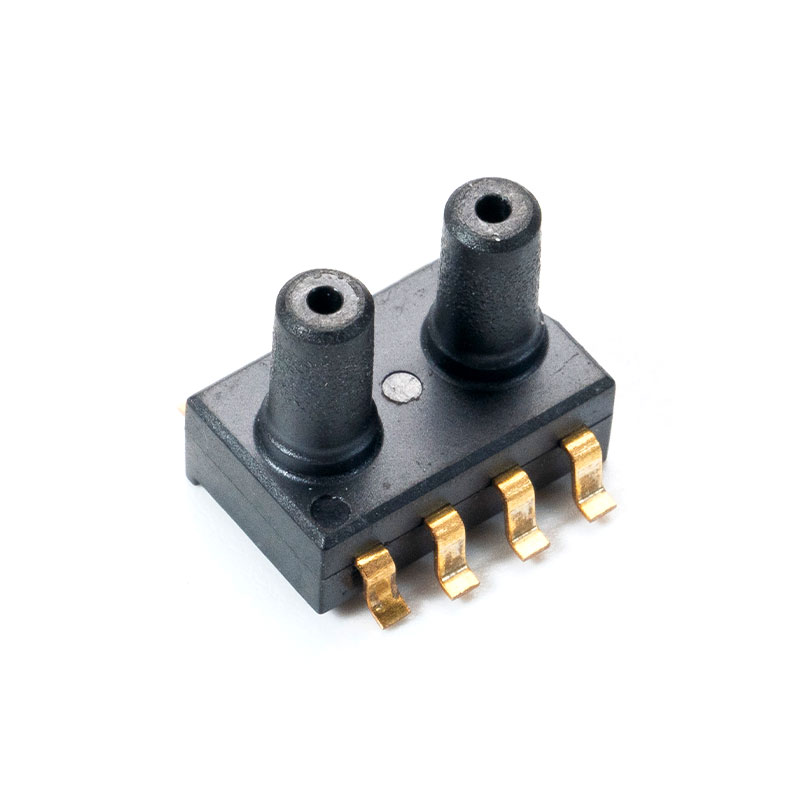

Mems Tech has specialized in the field of pressure sensors for over 14 years.
-
 [email protected]
-
 +86-18068257393
-
 50-1125 Zhongbang City Garden, No.2008 Taihu East Avenue, Xinwu District, Wuxi City, Jiangsu Province, China
Copyright © 2025 byWuxi Mems Tech Co., Ltd. Rights Reserved.
Custom MEMS Pressure Sensor Manufacturers
