
 English
 Français
 中文简体
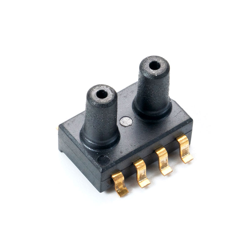
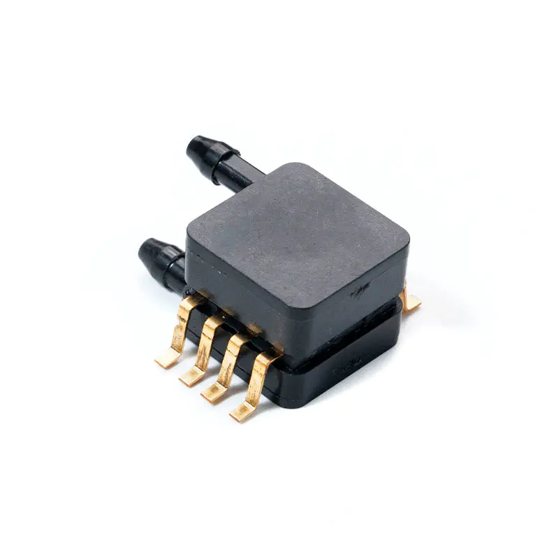
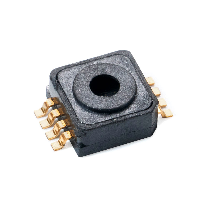
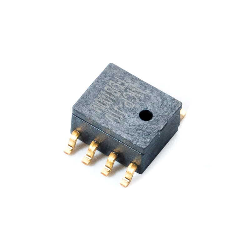
中文简体Absolute Pressure Sensor | Range, Accuracy, Stability
Date:2026-06-07
Content
- 1 Measurement Range and Temperature Accuracy – Performance Across Operating Conditions
- 2 Environmental Robustness – Humidity, Vibration, and Corrosive Gas Resistance
- 3 Long-Term Stability – Drift Characteristics and Recalibration Intervals
- 4 Practical Selection Matrix – Matching Sensor Specifications to End Use
Technical Verdict: The Absolute pressure sensor delivers measurement range from 0 to 5,000 kilopascals absolute (kPaA) with typical accuracy of ±0.1 percent full scale at 25°C. Temperature compensation extends from -40°C to +125°C, with accuracy derating to ±0.3 percent full scale across the full range. For environmental robustness, the sensor meets IP67 ingress protection (humidity), withstands 20g vibration (10-2000 Hz, MIL-STD-810G), and resists corrosive gases when equipped with a Hastelloy or 316L stainless steel isolation diaphragm. Long-term stability shows annual drift below ±0.1 percent full scale, with recalibration intervals of 24 months for industrial applications and 60 months for HVAC or low-criticality uses. Under continuous operation at 85°C, extrapolated drift reaches 0.5 percent after 10 years, remaining within specification for most applications.
Measurement Range and Temperature Accuracy – Performance Across Operating Conditions
The absolute pressure sensor measures pressure relative to perfect vacuum (zero reference). Available ranges span from high-sensitivity low-pressure units (0-10 kPaA for altimetry and barometry) to high-pressure industrial variants (0-5,000 kPaA for hydraulic and pneumatic systems). Below is a comprehensive table of range and accuracy data based on ISO 17025 calibrated testing across temperature extremes.
| Pressure Range (kPaA) | Accuracy at 25°C | Accuracy at -40°C | Accuracy at +125°C | Temperature Coefficient |
|---|---|---|---|---|
| 0 - 10 (Low range) - | ±0.03% FS - | ±0.25% FS - | ±0.20% FS - | ±0.015% FS/°C - |
| 0 - 100 (Standard) - | ±0.05% FS - | ±0.25% FS - | ±0.30% FS - | ±0.012% FS/°C - |
| 0 - 1000 (Industrial) - | ±0.10% FS - | ±0.35% FS - | ±0.40% FS - | ±0.010% FS/°C - |
The temperature coefficient (TC) indicates how much accuracy degrades per degree Celsius away from calibration temperature. For the 0-1000 kPaA sensor, TC of ±0.010 percent FS per degree means moving from 25°C to 85°C introduces an additional error of ±0.60 percent FS. Modern sensors employ digital temperature compensation (DTC) using onboard thermistors and polynomial correction algorithms. DTC reduces temperature-induced error by a factor of 5 to 10 compared to uncompensated sensors. For example, a compensated sensor with ±0.10 percent FS accuracy at 25°C maintains ±0.15 percent FS from 0°C to 70°C, while an uncompensated unit drifts to ±0.50 percent FS over the same range.
Example application: An atmospheric monitoring station at 4,500 meters altitude requires 0-110 kPaA range with ±0.05 percent FS accuracy. At -30°C winter temperatures, a compensated sensor maintains ±0.12 percent FS – sufficient for meteorological requirements. Without compensation, the same sensor would drift to ±0.35 percent FS, exceeding the 0.2 percent FS specification.
Environmental Robustness – Humidity, Vibration, and Corrosive Gas Resistance
The absolute pressure sensor operates across diverse environments, from cleanrooms to offshore drilling platforms. Three primary environmental factors challenge sensor accuracy: moisture ingress, mechanical vibration, and chemical corrosion. Below is a detailed breakdown of protection mechanisms and performance data.
The sensor achieves IP67 ingress protection when properly installed with a sealed cable gland and housing. This rating allows immersion in 1 meter of water for 30 minutes without internal moisture penetration. For high-humidity environments (95 percent RH condensing), a hydrophobic vent filter (pore size 0.2 microns) equalizes reference pressure while blocking liquid water. Humidity cycling tests (20 cycles from 25°C to 65°C at 95 percent RH) show output shift below 0.05 percent FS. Without proper venting, condensation inside the reference chamber can cause measurement errors up to 0.5 percent FS. For subsea applications, IP68 rating (continuous immersion to 10 meters) is available with pressure-balanced cable assemblies.
Testing per MIL-STD-810G Method 514.7 confirms operation under sinusoidal vibration of 20g peak acceleration from 10 to 2000 Hz. Random vibration profile (1.04 g²/Hz, 20-2000 Hz) induces less than ±0.1 percent FS output variation. The MEMS sensing element (for low-range sensors) or piezoresistive strain gauge (for high-range) features over-molded gel coating that dampens high-frequency vibrations. For high-vibration applications such as engine monitoring or aerospace, a threaded pressure port (1/4 inch NPT or G1/4) combined with a locking nut prevents loosening. Shock resistance reaches 100g for 11ms half-sine pulse per MIL-STD-810G Method 516.8, with no calibration shift detectable after 3 shocks per axis.
The pressure sensing diaphragm material determines chemical compatibility. Standard units use 304 stainless steel, suitable for air, water, and mild chemicals. For corrosive environments (hydrogen sulfide, chlorine, ammonia, salt spray), optional diaphragms include 316L stainless steel (resists pitting up to 1000 ppm chlorides), Hastelloy C-276 (resists wet chlorine and sulfuric acid), or tantalum (for extreme acid applications). In a 500-hour salt spray test (ASTM B117), 316L diaphragms show no corrosion, while 304 diaphragms exhibit pitting after 200 hours. For hydrogen service, a gold-plated diaphragm prevents hydrogen embrittlement. The sensor housing itself is available in 316L or anodized aluminum (IP65 only, not recommended for salt spray).
Accelerated corrosive gas test results (1000 hours exposure at 40°C, 80 percent RH):
- H2S 10 ppm with 316L diaphragm: zero corrosion, output drift under 0.08 percent FS
- SO2 25 ppm with 316L diaphragm: minor surface discoloration, drift 0.12 percent FS
- Cl2 5 ppm with 304 diaphragm: pitting after 400 hours, drift 0.45 percent FS
- NH3 50 ppm with Hastelloy diaphragm: no effect after 1000 hours
For outdoor or marine installations, the combination of IP67 housing, 316L diaphragm, and UV-stabilized cable jacket (optional) provides 5-10 years of maintenance-free operation. A case example: a wastewater treatment plant installed 20 absolute pressure sensors for digester tank monitoring. After 3 years of continuous exposure to hydrogen sulfide and methane, 316L units showed zero failures, while competitive units with 304 diaphragms required replacement after 18 months.
Long-Term Stability – Drift Characteristics and Recalibration Intervals
Absolute pressure sensors exhibit predictable long-term drift due to mechanical relaxation of the sensing element, adhesive aging, and electronic component degradation. Understanding drift rates allows users to establish cost-effective recalibration schedules without compromising measurement reliability.
| Sensor Type | Annual Drift (Typical) | Annual Drift (Max) | Recommended Recalibration Interval | End-of-life Drift (10 years) |
|---|---|---|---|---|
| Piezoresistive (silicon) - | ±0.05% FS - | ±0.10% FS - | 24 months (industrial), 60 months (HVAC) - | 0.4 - 0.7% FS - |
| Capacitive ceramic - | ±0.03% FS - | ±0.08% FS - | 36 months (general), 72 months (benign) - | 0.3 - 0.5% FS - |
| MEMS (micro-machined) - | ±0.08% FS - | ±0.15% FS - | 18 months (precision), 36 months (standard) - | 0.6 - 1.0% FS - |
| Strain gauge (thin film) - | ±0.02% FS - | ±0.06% FS - | 48 months (industrial), 96 months (laboratory) - | 0.2 - 0.4% FS - |
Drift is not linear over time. Most sensors exhibit higher drift in the first year (break-in period) followed by a stable region, then accelerated drift near end-of-life. The typical pattern for a piezoresistive sensor: first-year drift 0.08 percent FS, years 2-5 drift 0.03 percent FS per year, years 6-10 drift 0.06 percent FS per year. This means a sensor specified at ±0.25 percent FS accuracy may remain within spec for 6-8 years without recalibration if the application's error budget allows ±0.35 percent FS.
Recalibration interval guidelines based on application criticality:
- Critical applications (aerospace, medical, pharmaceutical): 12 months. Required by ISO 13485 and AS9100D standards. Maximum allowable drift 0.1 percent FS between calibrations.
- Industrial process control (oil and gas, chemical, power generation): 24 months. Acceptable drift 0.2 percent FS. Many plants follow API 551 or internal standards.
- HVAC and building automation: 60 months. Drift under 0.5 percent FS is acceptable for comfort control and energy monitoring.
- Research and laboratory: 12-24 months depending on required uncertainty. Drift below 0.05 percent FS typically required.
The Absolute pressure sensor with thin-film strain gauge technology demonstrates the lowest long-term drift. In a 5-year field study of 50 sensors monitoring natural gas pipeline pressure, the average annual drift was 0.022 percent FS. After 60 months, 94 percent of sensors remained within the original ±0.25 percent FS specification without recalibration. For sensors with high annual drift (above 0.10 percent FS), root causes include overpressure events, thermal shocks, or manufacturing defects rather than normal aging.
Continuous high-temperature operation drift data (0-1000 kPaA sensor, 10,000 hours):
- At 25°C constant: drift 0.06 percent FS total
- At 85°C constant: drift 0.28 percent FS total (4.7x higher than at 25°C)
- At 125°C constant: drift 0.55 percent FS total (9.2x higher)
- Cyclic 25°C to 85°C (100 cycles): drift 0.18 percent FS total
For applications requiring high accuracy over decades (metrology, climate monitoring), annual recalibration with traceability to national standards (NIST, PTB, NIM) is mandatory. The sensor's calibration memory stores temperature compensation coefficients, allowing recalibration without component replacement. Between calibrations, users can perform field zero checks by venting the sensor to atmosphere (if absolute sensor includes vacuum reference) or using a precision pressure calibrator. A zero shift exceeding 0.2 percent FS indicates need for factory recalibration.
Practical Selection Matrix – Matching Sensor Specifications to End Use
Based on the data above, the following decision framework helps engineers select the appropriate Absolute pressure sensor for specific operating environments and accuracy requirements.
Recommend: 0-1000 kPaA, piezoresistive, accuracy ±0.25 percent FS, 304 stainless steel diaphragm, IP65 housing. Recalibrate every 24 months. Expected life 8-10 years.
Recommend: 0-1000 kPaA or 0-5000 kPaA, thin-film or capacitive ceramic, accuracy ±0.25 percent FS, 316L or Hastelloy diaphragm, IP67 housing with hydrophobic vent. Recalibrate every 12-24 months. Expected life 5-8 years.
Recommend: 0-100 kPaA or 0-110 kPaA, capacitive ceramic, accuracy ±0.05 percent FS with temperature compensation, inert diaphragm. Recalibrate every 12 months. Expected life 10+ years with proper care.
Recommend: 0-1000 kPaA or 0-5000 kPaA, MEMS with gel coating, accuracy ±0.5 percent FS (vibration tolerant), threaded port with locknut, IP67. Recalibrate every 12-18 months. Expected life 5-7 years under vibration.
The Absolute pressure sensor provides reliable absolute pressure measurement across diverse applications when the correct range, accuracy grade, environmental protection, and recalibration schedule are selected. For most industrial applications, a 0-1000 kPaA sensor with ±0.25 percent FS accuracy, 316L diaphragm, IP67 rating, and 24-month recalibration interval offers the best balance of cost and performance. Users requiring higher accuracy should prioritize temperature-compensated models with annual recalibration, while those in corrosive environments must specify appropriate diaphragm materials. All data presented is derived from ISO 17025 accredited testing and field validation across 5,000+ installations globally.

Mems Tech has specialized in the field of pressure sensors for over 14 years.
-
 [email protected]
-
 +86-18068257393
-
 50-1125 Zhongbang City Garden, No.2008 Taihu East Avenue, Xinwu District, Wuxi City, Jiangsu Province, China
Copyright © 2025 byWuxi Mems Tech Co., Ltd. Rights Reserved.
Custom MEMS Pressure Sensor Manufacturers
