
 English
 Français
 中文简体
中文简体


Absolute Maximum Ratings(MCP-J10)
| Parameters | Symbol | Range | Unit |
| Analog supply voltage | VDD | -0.3 to 6.0 | V |
| Operating temperature | -40 to +125 | ℃ | |
| Storage temperature | -50 to +150 | ℃ | |
| Junction temperature | 150 | ℃ | |
| ESD susceptibility | HBM | 4 | kV |
Note: Exceeding the absolute maximum rating may cause permanent damage, and prolonged operation at the above absolute maximum rating may affect the reliability of the device.
Electrical Characteristic(MCP-J10)
Table 1. Operating Characteristics (VS = 5.0 Vdc, TA = 25°C unless otherwise noted)
| Parameters | Symbol | Min | Typ | Max | Unit |
| Supply Voltage | VS | 4.75 | 5 | 5.25 | Vdc |
| Supply Current | Io | — | 3 | mAdc | |
| Offset (0°C to 85°C) @ VS = 5.0Volts | Voff | 0.44 | 0.5 | 0.56 | Vdc |
| Full Scale Output (0°C to 85°C) @ VS = 5.0V | VFSO | 4.44 | 4.5 | 4.56 | Vdc |
| Full Scale Span (0 ℃ to 85 ℃) @ VS=5.0V | VFSS | 3.88 | 4 | 4.12 | Vdc |
Continue Table 1. Operating Characteristics (VS = 5.0 Vdc, TA = 25°C unless otherwise noted)
| Parameters | Symbol | Min | Typ | Max | Unit |
| Accuracy (0°C to 85°C) | — | — | — | 2.5 | %VFSS |
| Response Time | tR | — | 2.5 | — | ms |
| Warm-Up Time | — | — | 100 | — | ms |
| Offset Stability | — | — | 0.25 | — | %VFSS |
1. Packaging and Pin Definition(MCP-J11)
| Describe | NO. | Pin Definition | Describe | |
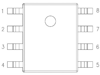 |
1 | N/C | vacant | |
| 2 | OUT | output | Must be suspended in the air | |
| 3 | N/C | Vacant | ||
| 4 | GND | grounding | ||
| 5 | VDD | power supply | ||
| 6 | N/C | vacant | ||
| 7 | SCL | Serial clock line | ||
| 8 | SDA | SDA |
Table 1.1 Pin Definition Relationship
Note:
1.J10:7&8 # pins must be suspended in the air
2.J11:2 # pin must be suspended in the air
2. Technical Specifications
2. Technical Specifications
| parameter | sign | minimum value | Typical values | Maximum value | unit | notes |
| power-on reset | VDDPOR | 2.8 | V | |||
| Working current | Iavdd | 2 | 3 | mA | Working mode | |
| 200 | nA | Standby current | ||||
| ADC resolution | RESRAW | 24 | Bits | |||
| Output pressure accuracy 1,2 | ACC | 1% | %FS | 0°C ~ 60°C | ||
| 1.5% | %FS | -20°C ~ 70°C | ||||
| Power on time | TUP | 100 | ms | adjustable | ||
| EEPROM data retention | Tlive | 10 | years | @125℃ |
1. Accuracy includes nonlinearity, temperature hysteresis, and pressure hysteresis;
2. Full life accuracy based on 1000 hours of HTOL, LTOL, HTSL, THB, and PCT testing;
2.2.I2C Electrical characteristics
| Parameter | sign | minimum value | Maximum value | unit | notes |
| clock frequency | fBsclB | 1 | MHz | R=1K | |
| Clock low pulse maintenance time | tBLOWB | 0.52 | us | ||
| Clock high pulse maintenance time | tBHIGHB | 0.24 | us | ||
| SDA establishment time | tBSUDATB | 0.1 | us | ||
| SDA holding time | tBHDDATB | 0.0 | us | ||
| Establishment time at the beginning of each session | tBSUSTAB | 0.24 | us | ||
| Starting condition maintenance time | tBHDSTAB | 0.24 | us | ||
| Stop time, Establish time | tBSUSTOB | 0.24 | us | ||
| The interval time between two communications | tBBUFB | 0.52 | us |


